


C7027A, C7035, C7044A, C7927A MINIPEEPER® ULTRAVIOLET FLAME DETECTORS
60-2026—11 6
Mounting a C7027A, C7927 or C7035A
Locate the Sight Pipe
The location of the sight pipe is the most critical part of the
installation. A black iron pipe is recommended. Do not use a
stainless steel or galvanized pipe because its internal surface
blackens with use as deposits from the combustion chamber
settle on it. Initially, its shiny internal surface reflects ultraviolet
radiation, which could result in a satisfactory flame signal,
even though the pipe may be improperly located. As it
blackens, less ultraviolet radiation is reflected and the flame
signal may become marginal.
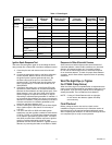
Under optimum sighting conditions, the C7027A , C7927 and
C7035A Flame Detectors can detect most common gas and
oil combustion flames at a distance of six feet. The critical
factors in determining the flame-detector distance separation
are the optimized flame signal (current or voltage) and the
flame detector temperature. Other factors may be influential
and are associated with the specific installation. For minimum
flame signals, see Table 1 and for ambient operating
temperatures, refer to Specifications, page 2.
Use 1/2 in. pipe for a C7027 or C7927, and 1 in. pipe for
a C7035. Since no two situations are likely to be the same,
length and sighting angle of the pipe must be determined at
the time and place of installation. Generally, it is desirable
to have the sight pipe tilting downward to prevent soot or dirt
buildup.
If a C7027A or C7927A is to be used for a blast tube
installation, its location should be determined by the burner
manufacturer; contact the manufacturer before making any
modifications to the installation.
In locations where water is usually sprayed on the body of the
detector, use a C7035A. Internal threads in its base permit the
use of waterproof flexible conduit for this type of application.
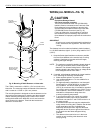
Prepare Hole In Wall Of Combustion Chamber
Cut a hole of the proper diameter for the sight pipe in the wall
of the combustion chamber at the selected location. Flare the
hole to leave room for small adjustments of the sighting angle.
The taper of the hole should be about 1 in. for every 3 in.
(25 mm for every 76 mm) of wall thickness.
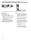
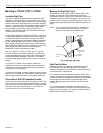
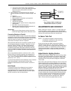
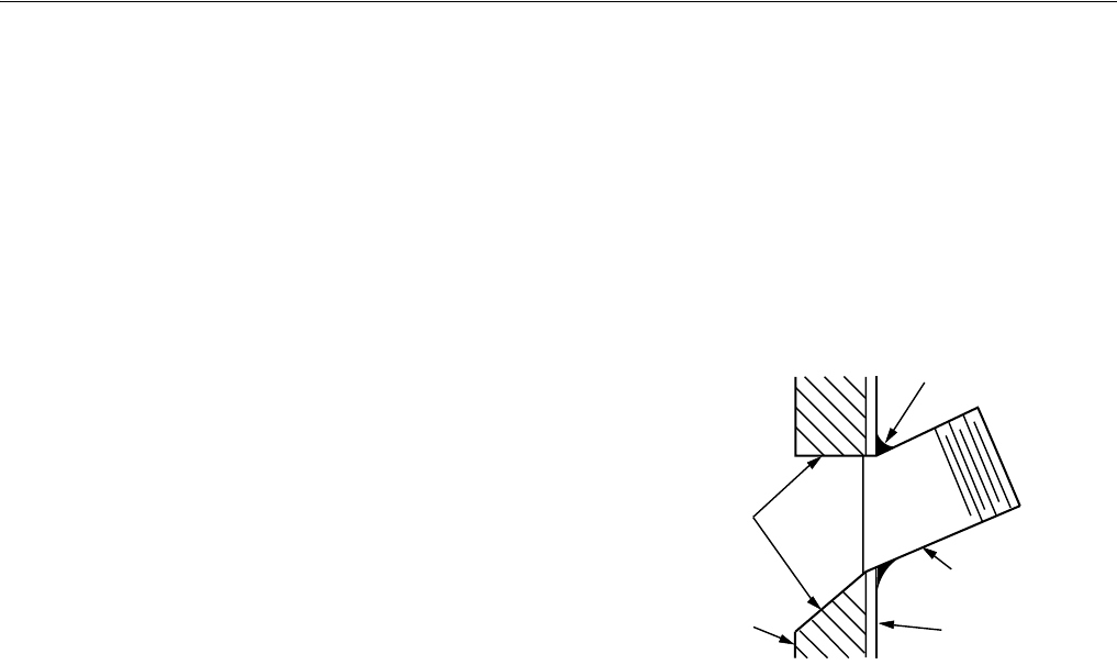
Mounting The Sight Pipe (Fig. 6)
Thread one end of the pipe to fit the mounting collar on the
detector. Cut the pipe to the desired length (as short as
practicable), and at an angle so it fits flush with the wall of the
combustion chamber. Tack-weld the pipe to the wall in a trial
position. Do not permanently weld the sight pipe in place until
after completing the Adjustments and Checkout beginning on
page 7.
NOTE: If you use a swivel mount (part no. 118367A) and
you are positive about the location and sighting
angle, you can permanently weld the pipe.
Fig. 5. Mounting sight pipe.
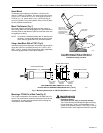
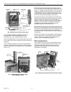
Sight Pipe Ventilation
It may be necessary to ventilate the sight pipe to cool the
flame detector or to clear the sight pipe of UV radiation
absorbing substances such as smoke, excessive moisture or,
in some instances, unburned fuel.
For a negative pressure combustion chamber, drilling a few
holes in the section of the sight pipe outside of the combustion
chamber will allow air at atmospheric pressure to flow through
the sight pipe into the chamber. A perforated pipe nipple
between the sight pipe and the detector can also be used
(see Fig. 7).
For a positive pressure combustion chamber, connect a
supply of pressurized air from the burner blower through the
sight pipe into the chamber. The supply air pressure must be
greater than the chamber pressure.
F
LARED HOLE
R
EFRACTORY
BOILER
PLATE
BLACK IRO
N
SIGHT PIPE
TEMPORARY
TACK WELD
M3019A