


11 60-2026—11
a
Currently obsolete.
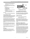
Ignition Spark Response Test
Test to be sure that ignition spark is not actuating the flame
relay (usually 2K) or flame LED in the flame safeguard control.
1. Close the pilot and main burner manual fuel shutoff
valves.
2. Connect the appropriate meter to the flame safeguard
control amplifier. Start the burner and run through
the ignition period. Ignition spark should occur, but
the flame relay must not pull in or the flame LED
should not light. The flame signal should not be more
than 0.25 microamp or 1.25 Vdc with the BC7700 or
7800 SERIES.
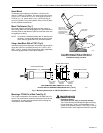
3. If the flame relay does pull in or the flame LED lights,
reposition the flame detector to increase the distance
between the flame detector and the ignition spark. If the
flame detector is not in the line of sight of the ignition
spark but appears to respond to the spark, it may be
responding to reflected spark generated UV radiation. If
so, relocate the flame detector so it does not receive the
reflected UV radiation. It may be necessary to construct
a barrier to block the UV radiation generated by the
spark from the flame detector view.
4. Continue making the adjustments until the flame signal
due to ignition spark is less than 0.25 microamp or
1.25 Vdc.
5. The use of the Q624 or Q652 solid-state ignition
transformer may also provide a method to eliminate the
C7027A, C7035A, or C7044A flame detector response
to UV radiation generated by ignition spark. The Q624
and Q652 prevents flame detector response to ignition
spark by providing alternating periods of spark
generation and UV sensor activation. If ignition spark is
detected, try reversing the leads on the Q624 or Q652.
Response to Other Ultraviolet Sources
Some sources of artificial light produce small amounts of
ultraviolet radiation. Under certain conditions, an ultraviolet
detector will respond to them as if it is sensing a flame.
Do not use an artificial light source to check the response
of an ultraviolet detector. To check for proper flame detector
operation, test for flame failure response under all operating
conditions.
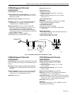
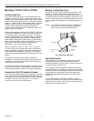
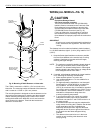
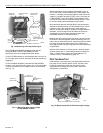
Weld The Sight Pipe (or Tighten
the C7044A Clamp Screw)
When the flame signal is acceptable after all adjustments are
made, remove the flame detector and weld the sight pipe in its
final position. If you are using a swivel mount, the pipe may
already be welded. Then reinstall the flame detector.
NOTE: If using a C7044A Detector with no sight pipe,
do not remove the detector; tighten the clamp
screw securely.
Final Checkout
Before putting the burner into service, check out the
installation using the procedures in the Checkout section of
the Instructions for the appropriate flame safeguard control.
After completing the checkout, run the burner through at least
one complete cycle to verify correct operation.
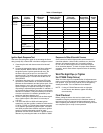
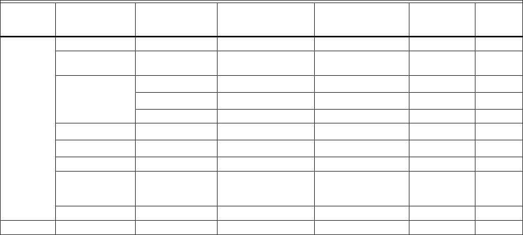
Table 1. Flame Signal.
Flame
Detector
Plug-in
Amplifier
Honeywell Flame
Safeguard
Control
Minimum Acceptable
Steady Current
(microamps)
Maximum Current
Expected
(microamps)
Minimum
Acceptable
Voltage (Vdc)
Maximum
Voltage
(Vdc)
C7027A,
C7035A,
C7044A
R7249A BC7000 + PM720 3.5 7.5 — —
R7749B
(AMPLICHECK™)
BCS7700A — — 2.2 4.98
R7249A
R4075C
a
,D
a
,E
a
3.5 7.5 — —
R4138C
a
,D
a
3.5 7.5 — —
R4140G,L,M 3.5 7.5 — —
R7290A
R4795A,D
a
1.5 2.25 — —
None
R7023C
a
1.5 2.25 — —
NONE R7795A,C,E,G 1.5 2.25 — —
R7849A or
R7849B
(AMPLICHECK™)
7800 SERIES — — 1.25 5.0
None RA890G 1.5 2.25 — —
C7927A R7851B 7800 SERIES — — 1.25 5.0