


C7027A, C7035, C7044A, C7927A MINIPEEPER® ULTRAVIOLET FLAME DETECTORS
5 60-2026—11
WARNING
Explosion Hazard and Electrical Shock Hazard.
Can cause serious injury, death or property
damage.
1. The C7027A, C7035A , C7044A and C7927 Flame
Detectors must be used with Honeywell flame
safeguard controls (primaries, programmers,
multiburner systems, and burner management
systems). Using with controls not manufactured by
Honeywell could result in unsafe conditions.
2. Disconnect power supply before beginning
installation to prevent electrical shock or equipment
damage, more than one disconnect may be
involved.
3. Read the installation instructions before starting the
installation.
4. All wiring must be NEC Class 1 (line voltage).
5. The flame detector must be positioned so that it
sights the flame and does not respond to the UV
radiation emitted by sparks generated by a spark
ignitor. The Q624A Solid-State Igniter may be useful
in difficult installations.
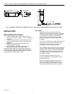
Basic Requirements For Ultraviolet
Detector Installations
All flames emit ultraviolet radiation, invisible to the human eye
but detected by the UV sensing tube. There are two important
factors in UV detector installation:
The detector must have a line-of-sight view of the flame.
The detector must not be exposed to other sources of
ultraviolet radiation, the most common being ignition spark.
Other sources are listed in the next section.
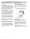
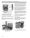
Because it is necessary for the detector to actually see the
flame, it is desirable to locate the detector as close to the
flame as physical arrangement and temperature restrictions
permit.
Sighting requirements for different types of flame supervision
are:
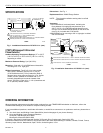
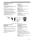
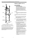
1. Pilot flame only—Sighting must be along the axis of the
pilot flame. The smallest pilot flame that can be sighted
must be capable of igniting the main burner (see Pilot
Turndown Test, page 9).
2. Main flame only—Sighting must be at the most stable
part of the flame for all firing rates.
3. Pilot and main flame—Sighting must be at the junction
of both flames.
Other Radiation Sources Sensed
By The UV Detector
Examples of radiation sources (other than flame) that could
actuate the detection system are:
1. Ultraviolet Sources:
a. Hot refractory above 2800°F (1371°C).
b. Spark.
c. Ignition transformers.
d. Welding arcs.
e. Lightning.
f. Gas lasers.
g. Sun lamps.
h. Germicidal lamps.
2. Gamma Ray and X-ray Sources:
a. Diffraction analyzers.
b. Electron microscopes.
c. Radiographic X-ray machines.
d. High voltage vacuum switches.
e. High voltage condensers.
f. Radioscotopes.
Except under unusual circumstances, none of these sources
except hot refractory and ignition spark would be present in or
near the combustion chamber.
The detector may respond to hot refractory above 2800°F
(1371°C) if the refractory surface represents a significant
percentage of the field of view of the detector. If the
temperature of the hot refractory causes the flame relay
(in the flame safeguard control) to pull in, re-position the sight
pipe so the detector views a cooler area of the refractory.
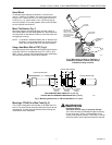
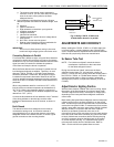
Ignition spark is a source of ultraviolet radiation. When
installing the C7027A, C7035A, C7044A or C7927 Flame
Detector, make sure it does not respond to ignition spark (see
Ultraviolet Response Test, page 9.) If the installation is such
that response to the ignition sparks cannot be avoided, the
Q624A Solid-State Ignition Transformer may eliminate the
ignition spark response. The Q624A, when properly installed,
prevents C7027A, C7035A, C7044A and C7927 ignition
spark response by alternately activating the spark generator
and the UV sensing tube.