


Manning AirAlert-96d Gas Monitor 19073 AIRALERT96D 05/2006 Prelim REVC Copyright © 2006 Honeywell Analytics. All Rights Reserved. 8
3 Wiring continued
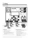
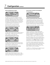
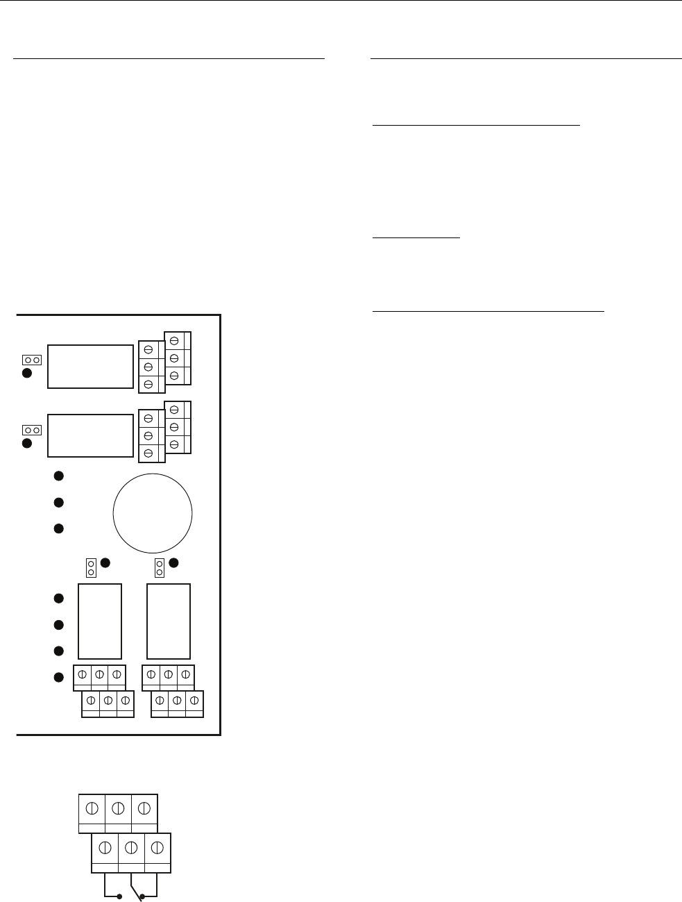
C Relay Outputs
The relay outputs will withstand up to 5 amps at
30 Vdc (resistive load only). They can be used to
activate horns and strobes. Refer to Figure 7 for
proper wiring. Each relay can be configured in the
PROGRAMMING MENU.
Default setting is:
Relay 1 (J25) = Warn
Relay 2 (J26) = Alarm
Relay 3 (J3) = High Alarm
Relay 4 (J7) = Fault
Relay rating: 5 A, 30 Vdc (resistive load)
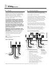
Figure 7. Relay Ouputs
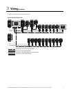
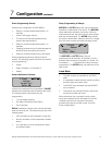
D Jumper Instructions
The different jumpers on the PCB enable the user
to make different operations manually.
Jumper EOL1, EOL2, EOL3, EOL4
: Enable the
user to add an END-OF-LINE jumper to improve
the communication signal. Two positions are
possible, R or RC. It can vary in accordance with
the system constraints. See the wiring detail for
the EOL position.
Jumper SHDN
: This jumper enables the user to
reset or shut down the microcontroller temporarily.
It is mainly used during minor modifications in the
wirings of the system.
Jumper RELAY J29, J30, J31, and J32
: They are
used to test the relay. Short pins to test.
Warn
Alarm
High Alarm
Power
Fault
TX
RX
System status LEDs
NC
NO
NC
NO
J3
J7
J26
J25
NO NC NO NC
Normally
open
Normally
closed
3+5
4+6
1+3
2+4
642
531
Relay 4
Relay 3
Relay 1 Relay 2
Relay Outputs (J3-J7-J25-J26)
5A, 30 Vdc or 120 Vac (resistive load)
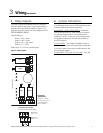
End-of-line
specification:
The E.O.L. jumper
for channels 1-2-3-4
must alwaysbe in
E.O.L. position