


Manning AirAlert-96d Gas Monitor 19073 AIRALERT96D 05/2006 Prelim REVC Copyright © 2006 Honeywell Analytics. All Rights Reserved. 5
3 Wiring
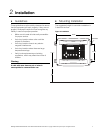
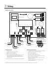
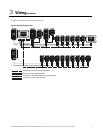
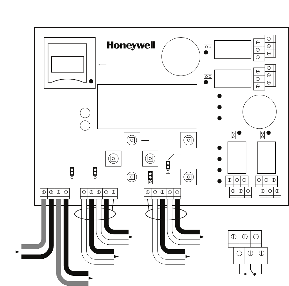
Figure 3. System Wiring
Warn
Alarm
High Alarm
Power
Fault
TX
RX
RC
R
EOL4
RC
R
EOL3
RC
R
EOL2
A1 B1 SHLD
A2
B2
V+ V-
V+
V-
SHLD A3 B4
B3
A4
System status LEDs
NC
NO
NC
NO
J3
J7
J26
J25
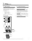
NO NC NO NC
Normally
open
Normally
closed
3+5
4+6
1+3
2+4
642
531
Previous
J22
J23
J24
In Out
Relay 4
Relay 3
Relay 1 Relay 2
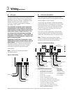
End-of-line
jumper position
RC
R
EOL1
Pushbutton
Relay Outputs (J3-J7-J25-J26)
5A, 30 Vdc or 120 Vac (resistive load)
Next
Channel 2
Channel 1
Channel 4
Channel 3
SD card datalogger
Power Requirements:
• 24 Vdc, 500 mA
• 14 AWG, 2 conductor, stranded cable
(Belden 5100UE or equivalent)
• Up to 10 sensors per power supply
• Up to 1,000 feet max power cable length per power supply
• Larger power cable and/or additional power supplies
may be required for longer cable runs and/or increased
number of sensors
Contact Honeywell Analytics for help with all power requirements.
Communication Requirements:
• 24 AWG twisted pair, shielded (Belden 9841 or equivalent)
• Network can be up to 2,000 feet per channel
• Avoid “T-taps” if possible
• Do not exceed 65 feet per T-tap
• Do not exceen 130 feet total of all T-taps
• Communication wire shield must be connected to shield
terminal(s) of controller (J23-J24)
• Channels 1-2-3: Modbus protocol — Communicates only
with Modbus devices
• Channel 4: Modbus output only — No sensor can be
connected to Channel 4