


Manning AirAlert-96d Gas Monitor 19073 AIRALERT96D 05/2006 Prelim REVC Copyright © 2006 Honeywell Analytics. All Rights Reserved. 7
3 Wiring continued
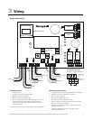
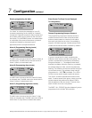
A Power
The power requirement range for the AirAlert
TM
96d
controller is 24 Vdc, 500 mA. The system must be
grounded to the power supply. A dedicated circuit
breaker should be used. Use 14 AWG two
conductor, stranded cable (Belden 5100UE or
equivalent), up to 1,000 ft.
If the controller is sharing a power supply with
multiple sensors on the network, care must be
taken to observe voltage drops (line loss) on the
power cable. Supply voltages less than 17 Vdc
can render some network devices inoperable.
Any supply voltage less than 17 Vdc requires the
installation of an additional power supply at that
point on the power cable.
Depending on total power consumption, avoid
powering more than 10 network devices with one
power supply. Additional power supplies and/or
decreased number of network devices may be
required to compensate for line loss. Contact
Honeywell Analytics for help with all power
requirements.
Note: Terminal J27 must be grounded to
mechanical ground.
Figure 5. Power Wiring
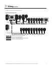
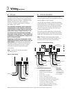
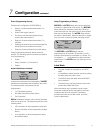
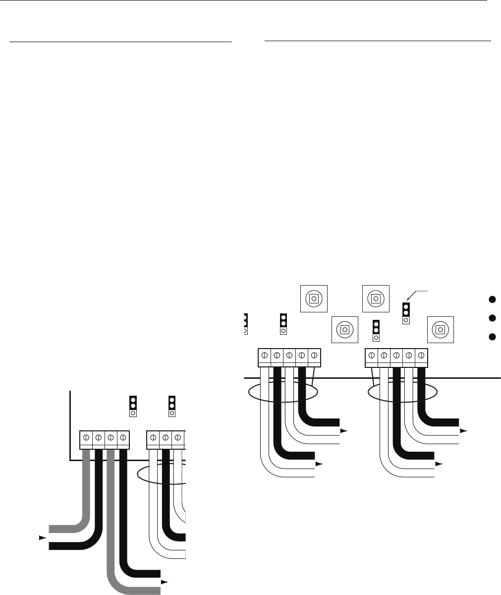
B Communication
The communication cables have to be grounded
using the shield terminal. Up to 32 network devices
can be installed on each channel.
Use 24 AWG two conductor, twisted and shielded
cable (Belden 9841 or equivalent) for the connection.
The network can be up to 2,000 feet per channel.
The length of a T-tap can be a maximum of 65 feet
(20 m). A maximum of 130 feet (40 m) for all the
T-taps must be respected.
The communication cables have to be grounded
using the shield terminal. Use twisted and shielded
cable #24/2 AWG (Belden 9841) for the connection.
Note: Channel 4 is the slave communication
channel to retransmit the MODBUS signal to PLC.
No sensor can be connected to this channel.
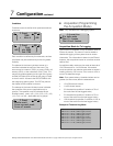
Figure 6. Communications Wiring
RC
R
EOL3
RC
R
EOL2
A1 B1
A2
V+ V-
V+
V-
Previous
J22
J23
In Out
Next
Powe
r
Fault
TX
RX
RC
R
EOL4
RC
R
EOL3
RC
R
A1 B1 SHLD
A2
B2
SHLD A3 B4
B3
A4
J23
J24
End-of-line
jumper position
RC
R
EOL1
Channel 2
Channel 1
Channel 4
Channel 3
Communication Requirements:
• 24 AWG twisted pair, shielded
(Belden 9841 or equivalent)
• Network can be up to 2,000 feet
per channel
• Avoid “T-taps” if possible
• Do not exceed 65 feet per T-tap
• Do not exceen 130 feet total of all T-taps
• Communication wire shield must be connected
to shield terminal(s) of controller (J23-J24)
• Channels 1-2-3: Modbus protocol —
Communicates only with Modbus devices
• Channel 4: Modbus output only — No sensor
can be connected to Channel 4
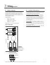
End-of-line
specification:
The E.O.L. jumper
for channels 1-2-3-4
must alwaysbe in
E.O.L.
p
osition