


Manning AirAlert-96d Gas Monitor 19073 AIRALERT96D 05/2006 Prelim REVC Copyright © 2006 Honeywell Analytics. All Rights Reserved. 23
10 Relay Module (optional) continued
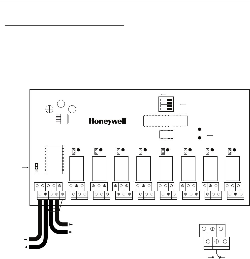
Wiring Details
Power Supply Cable
• 14 AWG stranded cable or larger (see your network
diagram provided by Honeywell Analytics sales
department).
Communication Cable
• 24 AWG twisted pair (Belden # 9841 or equivalent).
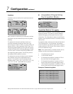
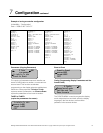
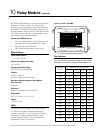
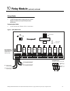
Figure 11. Relay Module PCB
Power
Tx Modbus
Normally
open
Normally
closed
3+5
4+6
1+3
2+4
642
531
RC
R
EOL1
Relay Outputs (J1-J8)
5A, 30 Vdc or 120 Vac (resistive load)
V+ V- SHLD
A
B
J10
J10
J8
J7
J2
J1
From “B” terminal of controller
to “B” terminal of next device
From “A” terminal of controller
to “A” terminal of next device
From +24VDC terminal
of power supply
From Ground terminal
of power supply
NO NCNO NC
Relay 2
NO NC
Relay 3 Relay 1
NO NC
Relay 4
NO NCNO NC
Relay 6
NO NC
Relay 7 Relay 5
NO NC
Relay 8
End of Line Resistor
On the last device of the
communication network,
a jumper must be
installed as shown.
Power and TX
status LEDs
1
2
3
4
off
DIP switches