


FM USER INSTRUCTIONS ENGLISH 71576526 - 03/07
Page 22 of 32 flowserve.com
5.7 Hydraulic, mechanical and electrical
duty
This product has been supplied to meet the
performance specifications of your purchase order,
however it is understood that during the life of the
product these may change. The following notes may
help the user decide how to evaluate the
implications of any change. If in doubt contact your
nearest Flowserve office.
5.7.1 Specific gravity (SG)
Pump capacity and total head in meters (feet) do not
change with SG, however pressure displayed on a
pressure gauge is directly proportional to SG. Power
absorbed is also directly proportional to SG. It is
therefore important to check that any change in SG
will not overload the pump driver or over-pressurize
the pump.
5.7.2 Viscosity
For a given flow rate the total head reduces with
increased viscosity and increases with reduced
viscosity. Also for a given flow rate the power
absorbed increases with increased viscosity, and
reduces with reduced viscosity. It is important that
checks are made with your nearest Flowserve office
if changes in viscosity are planned.
5.7.3 Pump speed
Changing pump speed effects flow, total head,
power absorbed, NPSH
R
, noise and vibration. Flow
varies in direct proportion to pump speed, head
varies as speed ratio squared and power varies as
speed ratio cubed. The new duty, however, will also
be dependent on the system curve. If increasing the
speed, it is important therefore to ensure the
maximum pump working pressure is not exceeded,
the driver is not overloaded, NPSH
A
> NPSH
R
, and
that noise and vibration are within local requirements
and regulations.
5.7.4 Net positive suction head (NPSH
A
)
NPSH available (NPSH
A
) is the head available at the
impeller inlet, above the vapor pressure of the
pumped liquid.
NPSH required (NPSH
R
) is the minimum head required
at the impeller inlet, above thevapor pressure of the
pumped liquid, to avoidexcessive cavitation and
extreme performance degradation.
It is important that NPSH
A
> NPSH
R
. The margin
between NPSH
A
> NPSH
R
should be as large as
possible.
If any change in NPSH
A
is proposed, ensure these
margins are not significantly eroded. Refer to the
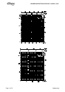
pump performance curve to determine exact
requirements particularly if flow has changed.
If in doubt please consult your nearest Flowserve
office for advice and details of the minimum
allowable margin for your application.
5.7.5 Pumped flow
Flow must not fall outside the minimum and
maximum continuous safe flow shown on the pump
performance curve and or data sheet.
5.8 Pumps for Food Use or Potable
Water
If the pump has not been specifically ordered for a food
or drinking water application it must not be used for
these types of applications. If it has been ordered for
this type of application the following recommendations
are to be followed.
5.8.1 Cleaning prior to operation
Pumps that are to be used for a food or drinking water
applicationshould be cleaned before being put into
initial operation and after the installation of spare parts
that are incontact with the liquid.
Cleaningonce the pump has been commissioned will
depend on the application and operating conditions.
The user must ensure that the cleaning procedures are
suitable for the application and operating conditions,
and local regulations.
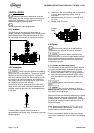
6 MAINTENANCE
6.1 General
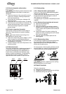
If a belt drive is used, the assembly and
tension of the belts must be verified during regular
maintenance procedure.
In dirty or dusty environments, regular checks
must be made and dirt removed from areas around
close clearances, bearing housings and motors.
It is the plant operator's responsibility to
ensure that all maintenance, inspection and
assembly work is carried out by authorized and
qualified personnel who have adequately
familiarized themselves with the subject matter by
studying this manual in detail (see also section
1.6.2).
Any work on the machine must be performed when it
is at a standstill. It is imperative that the procedure
for shutting down the machine is followed, as
described in section 5.6.
On completion of work all guards and safety devices
must be re-installed and made operative again.