


FM USER INSTRUCTIONS ENGLISH 71576526 - 03/07
Page 16 of 32 flowserve.com
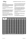
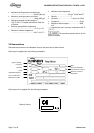
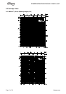
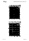
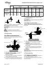
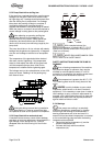
Forces
daN (lbf)
Moments
m.daN (lbf.ft)
DN
F
Y
F
Z
F
X F
M
Y
M
Z
M
X M
40
(1"1/2)
30
(67)
40
(90)
35
(79)
60
(135)
23
(170)
27
(199)
34
(251)
49
(361)
Vertical pipework
perpendicular to
the shaft
50
(2")
40
(90)
50
(112)
45
(101)
80
(180)
27
(199)
30
(221)
37
(273)
54
(398)
50
(2")
45
(101)
40
(90)
50
(112)
80
(180)
27
(199)
30
(221)
37
(273)
54
(398)
Axial pipework
parallel to the
axis
65
(2"1/2)
58
(130)
50
(112)
68
(153)
102
(229)
30
(221)
33
(243)
40
(295)
60
(443)
Forces and moments values are applied to the
whole flanges and not flange by flange.
Ensure piping and fittings are flushed
before use.
Ensure piping for hazardous liquids is
arranged to allow pump flushing before removal of
the pump
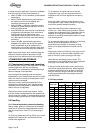
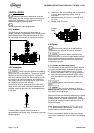
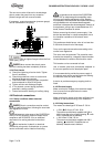
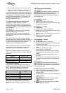
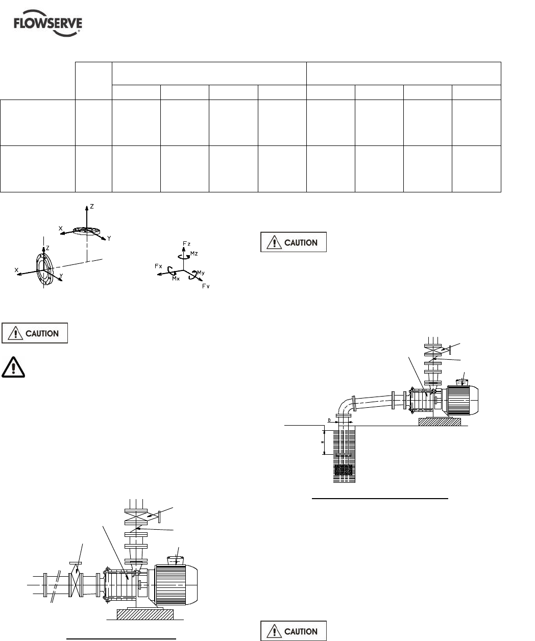
4.3.2 Suction piping
4.3.2.1 Design of a flooded suction line
The suction line must be as short and direct as
possible, never mount an elbow directly on the inlet
flange of the pump.
Valve
Non-return valve
Motor
FM
Continuous flow valve
Flooded suction pump
a) Avoid sharp elbows or sudden narrowing. Use
convergent 20° (total angle).
b) Arrange the piping so that there are no air
pockets (no bulges).
c) If high points cannot be avoided in suction line,
provide them with air relief cocks.
d) If a strainer is necessary, its net area should be
three or four times the area of the suction pipe.
e) If an inlet valve is necessary, choose a model
with direct crossing.
Do not tighten flanges before the final
check (see § 4.3.4).
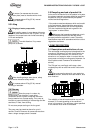
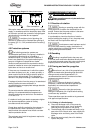
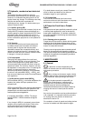
4.3.2.2 Design of a suction lift line
The inlet pipe must be as short and as direct as
possible, never place an elbow directly on the pump
inlet nozzle.
Valve
Non-return valve
Motor
FM
Sufficient
immersion: I
I 3 x D
Sump suction configuration
a) Avoid sharp elbows or sudden narrowing. Use
convergent 20° (total angle) with upright
generating.
b) Arrange that the suction piping is inclined
upwards towards the pump ensuring that there
are no peaks.
c) If a foot valve is necessary, do not oversize it
because it would generate pulsations (valve
beating).
Do not tighten flanges before the final
check (see § 4.3.4).
4.3.3 Discharge piping
4.3.3.1 Design of a discharge line
a) If discharge line is provided with a divergent, its
total angle will be between 7° and 12°.
b) Install the discharge valve after the non-return
valve downstream.