


FM USER INSTRUCTIONS ENGLISH 71576526 - 03/07
Page 17 of 32 flowserve.com
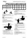
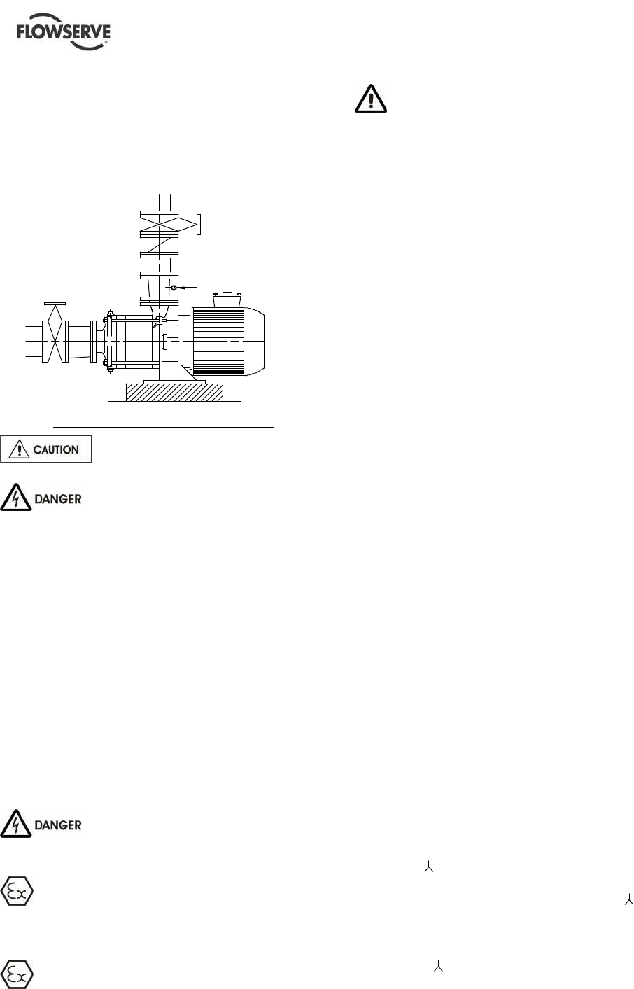
The non-return valve will be set in the discharge
pipe to protect the pump from any excessive
pressure surge and from reverse rotation.
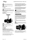
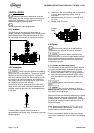
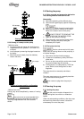
If necessary, a control manometer (pressure gauge)
can be connected on the piping.
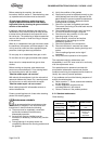
Control manometer
Setting of the control manometer
Do not tighten flanges before the final
check (see § 4.3.4).
Never connect the electric motor
before the setting has been completely finished.
4.3.4 Final checks
a) Check the tightening of anchor bolts. Tighten
them if necessary.
b) Check that protective covers on suction and
discharge flanges are removed.
c) Check that holes of piping flanges are parallel
and correspond to those of the pump.
d) Tighten suction and discharge flanges.
e) If it is planned, connect piping(hydraulic,
pneumatic, sealing system).
f) Control seal and the working of auxiliary piping.
4.4 Electrical connections
4.4.1 Safety conditions about electrical
connections
Electric connections must be carried
out by a qualified electrician, following the local rules
and regulations in force.
It is important to be aware of the EUROPEAN
DIRECTIVE on potentially explosive areas where
compliance with IEC60079-14 is an additional
requirement for making electrical connections.
Avoid mechanical, hydraulic or electrical
overload by using motor overload trips or a power
monitor and make routine vibration monitoring.
It is important to be aware of the EUROPEAN
DIRECTIVE on electromagnetic compatibility when
wiring up and installing equipment on site. Attention
must be paid to ensure that the techniques used during
wiring/installation do not increase electromagnetic
emissions or decrease the electromagnetic immunity of
the equipment, wiring or any connected devices. If in
doubt, contact Flowserve for advice.
Before connecting the electric power supply, if the
device has been kept in a damp atmosphere, have
the insulation resistance of the electric motor
checked.
This resistance should have a value of not less than
5 000 ohms for each volt of the supply.
Carry out the ground connections according to the
current local regulations.
The motor must be protected. The protection must
therefore be ensured by a magneto thermal breaker
located between the section switch and the motor.
This breaker can be connected to fuses.
Use a breaker sized and provisionally adjusted to
the current specified on the description plate.
It is recommended to provide the power supply of
the electric motor with a monitoring device allowing
the machine to be shut down safely.
A device to provide emergency stopping shall be
fitted.
4.4.2 Electrical supply
Make sure that the voltage of the electrical supply
line is correct for that specified on the motor
description plate.
Make sure that the supply wires have sufficient load
capacity for the correct running of the installation.
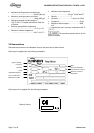
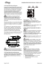
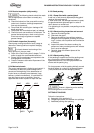
4.4.3 Wiring Instructions
The motors are closed type IP 55 class E - 50 Hz
230/ 400 V up to 3.7 kW - 50 H:
The motors can be directly supplied with 230 or
400 V according to the coupling (starting with
230 V is possible but not advised)
400 V from 5.5 kW -50 Hz:
The motors can be directly supplied with 400 V
(starting with 400 V is possible but not
advised). Astatoric start is advised.