


9
FLINT & WALLING, INC. • 95 North Oak St. • Kendallville, IN 46755 • www.flintandwalling.com
Operation (Continued)
MOTOR/PUMP ROTATION
1. Single phase models are one (1) rotation only (counter-
clockwise when facing the pump end) and cannot be
reversed.
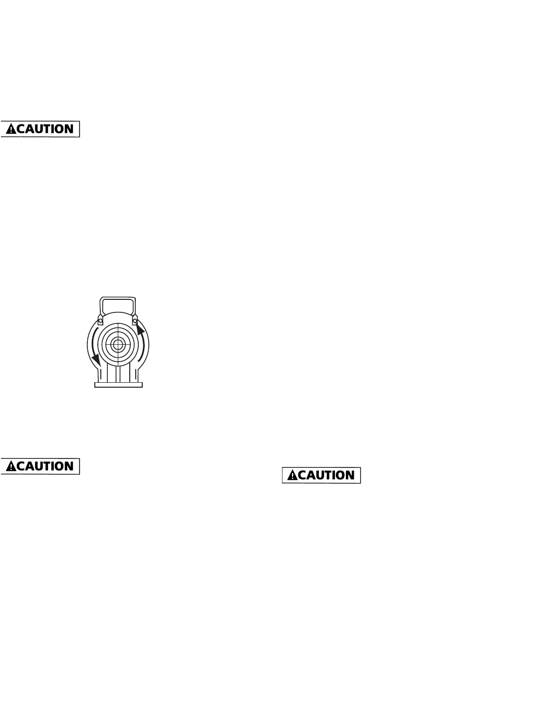
2. Proper rotation of pump impeller is critical for three phase
pumps. Pump motor should turn counterclockwise (CCW)
when facing pump end. Momentarily “bump” (apply
power for less than a second) the motor to check for
proper rotation. To change rotation on three phase units,
interchange any two (2) incoming line (power) leads.
Do not go over recommended maximum
operating pressure (see Specifications), while maintaining
minimum flow of 1.5 GPM thru the pump. Do not restrict
the inlet line to the pump.
If driver (electric motor) is overloaded, a valve can be
installed in the discharge line to increase the back pressure
and reduce driver loading.
START - UP PROCEDURE
Once the preceding instructions have been completed, the
pump can be started.
1. During the first few hours of operation, inspect the pump,
piping and any auxiliary equipment used in connection
with the unit.
2. Check for leaks, excessive vibration or unusual noises.
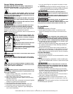
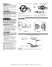
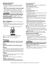
Figure 12 - Correct Motor/Pump Rotation (all units)
NOTE: See rotation arrow on inlet casting.
IL0539
Maintenance
Disconnect power supply and depressur-
ize system before servicing pump or removing any compo-
nent.
ROUTINE
Pump should be checked routinely for proper operation.
Replace or clean all filters and line strainers on a regular
basis.
DRAINING
This pump cannot be completely drained because of internal
design. Most of the liquid can be drained by tilting the dis-
charge forward after removing discharge casting; or, the liq-
uid can be drained through the inlet port. Store in heated
areas.
CLEANING
If used for spraying insecticides, pump should be thoroughly
flushed with clean water after using.
LUBRICATION
The motor has prelubricated bearings. No lubrication is
required.
SERVICING THREE-PHASE UNITS
Loctite (thread sealer) is used on the threads between the
motor shaft and the pump shaft coupling. When reassem-
bling, reapply thread sealer.
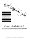
PUMP DISASSEMBLY
To disassemble the pump, refer to the exploded parts view,
Figures 17 & 18 Tools Required
• Block of wood (2” x 4” x 12”)
Piece of 3/4” pipe (12” to 24” long)
• Pipe wrench
• Strap wrench
• 1/4” Dowel rod (about 24” long)
• 9/16” Open end wrench
• 3/8” Open end wrench
1. To stabilize pump during disassembly, place block of wood
underneath pump barrel.
2. Thread pipe into pump inlet port. This acts as a handle.
3. Using the pipe wrench, remove the discharge head, turn-
ing CCW (counter clockwise).
4. With the strap wrench, loosen the barrel, turning CCW
(counter clockwise). DO NOT use pipe wrench on pump
barrel.
5. Holding the impeller stack in place, position pump in
upright position, standing unit on the motor end cover.
6. Use the 1/4” dowel rod to hold the stages down and in
place on the pump shaft. Remove pump barrel.
7. Slide the stages off the pump shaft onto the 1/4” dowel
rod. Leave stages on rod and carefully set aside.
NOTE: There may be some small .010” shim washers located
next to the pump shaft coupling. Keep these shims for re-
assembly.
8. Through the side opening of the mounting frame, hold
the motor shaft with 9/16” wrench. Remove the shaft and
coupling from the motor using the 3/8” wrench on the hex
shaped pump shaft.
NOTE: If the hex shaft comes free, leaving the coupling
attached to the motor, use vise grips to free the coupling.
MECHANICAL SEAL REPLACEMENT
1. Follow instructions under “Pump Disassembly”.
2. Remove the mechanical seal assembly.
a. The rotary portion of the seal assembly (carbon ring,
Buna-N gasket and spring will slide easily off the end of
shaft).
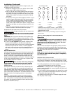
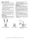
b. Using two (2) screwdrivers, pry the ceramic seal and rub-
ber gasket from the recess of the mounting ring (See
Figure 14).
The precision lapped faces of the mechan-
ical seal are easily damaged. Handle the replacement seal
carefully. Short seal life will result if seal faces (ceramic &
carbon) are nicked, scratched or dirty.
3. Clean the seal cavity of the mounting ring and the motor
thoroughly.
4. Wet outer edge of rubber cup on ceramic seat with liquid
soap solution. Use sparingly (one drop only).