


6
FLINT & WALLING, INC. • 95 North Oak St. • Kendallville, IN 46755 • www.flintandwalling.com
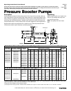
Installation (Continued)
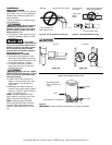
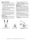
5. A pressure gauge installed in the
inlet pipe close to the inlet port, (See
Figure 6) will show if enough water
is being supplied to the pump. See
Operation Section - Priming, Pressure
Boost Installations.
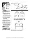
6. On installations that are using noz-
zles for mist spraying, install a filter
in the discharge plumbing to prevent
the nozzles from becoming plugged.
Multiple filters should be plumbed in
parallel.
!
Install a pressure
relief valve on any installation where
pump pressure can exceed the pressure
tank’s maximum working pressure or
on systems where the discharge line
can be shut off or obstructed. Extreme
over pressure can result in personal
injury or property damage.
This unit is not
waterproof and is not intended to
be used in showers, saunas or other
potentially wet locations. The motor
is designed to be used in a clean dry
location with access to an adequate
supply of cooling air. Ambient tem-
perature around the motor should
not exceed 104ºF (40ºC). For outdoor
installations, motor must be protected
by a cover that does not block airflow
to and around the motor. This unit is
not weatherproof nor is it able to be
submersed in water or any other liq-
uid.
To avoid dangerous or fatal elec-
trical shock, turn off power to motor
before working on electrical connec-
tions.
Supply voltage must be within ±
10% of nameplate voltage. Incorrect
voltage can cause fire or seriously
damage motor and voids warranty. If
in doubt, consult a licensed electrician.
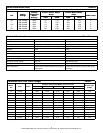
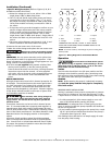
Use wire size specified in wiring
Chart F. If possible, connect pump
to a separate branch circuit with no
other appliances on it. If motor wiring
diagram differs from diagram shown
below, follow diagram on motor.
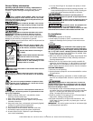
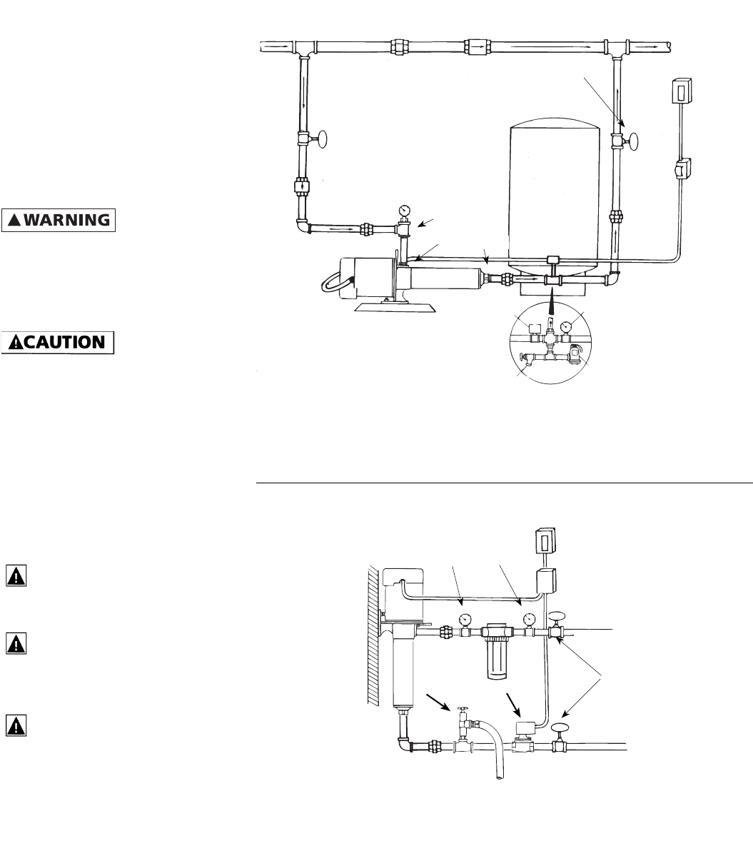
Figure 6
IMPORTANT: A contained air pressure tank and pressure switch is required to
keep the pump from rapid cycling and prevent the motor from over heating.
Install the tank and switch on the house side of system.
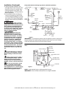
Pump used to boost water pressure in mist spray applications (automatic opera-
tion).
NOTE: Install solenoid valve on discharge side of pump.
Pump used to boost incoming city pressure (automatic operation).
IMPORTANT: Clean all filters and strainers on a regular schedule.
IL0423
IL0422
Street Supply
Union
Check Valve
Gate/Ball
Valve
(Normally
open)
Main Power Box
Fuse
Box or
Switch
Union
Pressure
Gauge
Drain
To size tank
properly - Match
drawdown of
tank to capacity
of pump
Union
Pressure
Relief
Valve
Pressure
Switch
Pressure Switch
Gate/Ball
Valve
(Normally
open)
Inlet
Pressure
Gauge
Check
Valve
Outlet
Service Tee
Fuse Box
or Switch
Thermostat
Gate/Ball Valve
From Water Source
Gate/Ball Valve
(Normally open)
To Nozzles
To Drain
Pressure Gauge
Line Filter
Solenoid
Valve
Pressure
Relief
Valve
Figure 7