


7
FLINT & WALLING, INC. • 95 North Oak St. • Kendallville, IN 46755 • www.flintandwalling.com
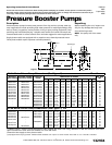
Installation (Continued)
Proper rotation of
pump impeller is critical on three phase
motors. See Motor Rotation under
Operation section and Figure 12.
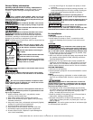
WIRING
1. Install, ground, wire and maintain
this pump in accordance with your
local electrical code and all other
codes and ordinances that apply.
Consult your local building inspector
for local code information.
2. Ground the pump permanently using
a wire of size and type specified
by local or United States National
Electrical Code. Do not ground to
a gas supply line.
3.Connect ground wire first. Connect
to ground first, then to green ground-
ing terminal provided on the motor
frame, identified as GRD. Ground con-
nection MUST be made to this termi-
nal. Do not connect motor to electrical
power supply until unit is permanently
grounded; otherwise serious or fatal
electrical shock hazard may be caused.
4. Connect the other end of the ground
wire to a properly grounded service
panel or to a control panel ground
bar if it is connected to the power
supply ground.
IMPORTANT: Check local and/or
United States National Electric Codes
for proper grounding information.
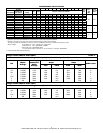
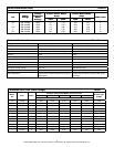
Make certain that
the power supply conforms to the elec-
trical specifications of the motor sup-
plied. See Motor Data Charts.
Ground motor
before connecting to
electrical power sup-
ply.
Failure to ground
motor can cause
severe or fatal electri-
cal shock hazard.
Do not ground to
a gas supply line.
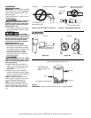
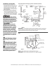
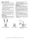
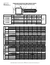
Pump used to boost incoming pressure from a wall hydrant (manual operation).
Figure 8
IL0424
Wall Hydrant
Hose Adapter
Pressure Gauge
Pressure
Relief Valve
Hose Adapter
High Pressure Reinforced Hose
Spray
Nozzle
Service Tee
Outlet
Inlet
High Pressure Reinforced Hose
Hazardous
voltage. Can
shock, burn or
cause death.
Ground pump
before connecting
to power supply.
!
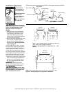
NOTE: Single voltage (230V) motor, and can not be connected to 115V.
IL0181
230 Volts
Single Phase
Line
L1 L2
AB
Figure 10 - Wiring Diagram for Single Phase 3 HP Motors
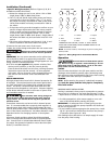
IL0180
NOTE: Dual voltage motors, change the red and
gray wire to the voltage required.
Figure 9 - Wiring Diagram for Single Phase 1/3 - 2 HP
Motors
115 Volts
Single Phase
230 Volts
Single Phase
Line
Line
L1
L1
L2 L2
A
A
B
B
Y
E
L
L
O
W
Y
E
L
L
O
W
W
H
I
T
E
G
R
A
Y
R
E
D
T
A
N
W
H
I
T
E
G
R
A
Y
R
E
D
T
A
N
Y
E
L
L
O
W
G
R
A
Y