


8
FLINT & WALLING, INC. • 95 North Oak St. • Kendallville, IN 46755 • www.flintandwalling.com
Installation (Continued)
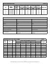
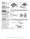
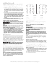
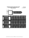
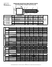
5.Specific Wiring Procedure (Refer to Figures 9, 10, & 11
and Minimum Wire Size Chart).
a. Select the voltage you are to use, either 115V or 230V
single phase, 230V or 460V three phase.
b. The 1/3, 1/2 and 3/4 HP single phase pumps are factory
connected for 115V at the motor. The 1, 1
1
/2, 2 and 3
HP pumps are factory connected for 230V at the motor.
Three phase models are factory connected for 230V at
the motor.
c. If the motor wiring must be changed to conform to your
specific voltage requirements then the motor, pressure
switch or other controls should be rewired to conform
to one of the wiring diagrams (either 115V or 230V,
single phase; 230V or 460V, three phase). Single phase 3
HP motors are 230V only and cannot be wired for 115V
service.
d. The motor wiring diagrams are Figures 9, 10, & 11 and
also are located on the motor label of the pump.
6. Remove the rear access cover of the motor.
7. Make the wiring change and replace the rear access cover.
!
Replace rear access cover before starting
or operating pump. Failure to do so can result in personal
injury.
IMPORTANT: Do not use an extension cord or splice wires.
Joints should be made in an approved junction box. If the
above information or the following wiring diagrams are con-
fusing, consult a licensed electrician.
8. All units are not supplied with pressure switches, float
devices, on/off switches, or the like (control devices).
Controls should be wired in at this time, utilizing whatever
instructions come with the controls. All units supplied
with cords, will run whenever cord is plugged into power
and will turn off whenever cord is disconnected from
power.
MOTOR PROTECTION
All single phase motors have built in thermal protection for
all voltages. The overload protects the motor against burn-
out from overload of low voltage, high voltage and other
causes. The device is automatic and resets itself once the
temperature has dropped to a safe point. Frequent tripping
of the device indicates trouble in the motor or power lines
and immediate attention is needed.
!
Never examine, make wiring changes or
touch the motor before disconnecting the main electrical
supply switch. The thermal device may have opened the
electrical circuit.
Three phase motors do not have a built in thermal protec-
tion. It is recommended that a properly sized magnetic or
manual starter (both with properly sized heaters) be used
with all three phase motors. Install starters following instruc-
tions of the starter manufacturer. See Motor Rotation under
Operation Section for changing rotation on three phase
motors.
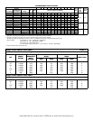
All motors (single and three phase) should be equipped
with a correctly fused disconnect switch to provide protec-
tion. Consult local or United States National Electric Codes
for proper fuse protection based on motor data chart (See
Charts C, D and Wire chart F).
Operation
Unit must be full of fluid before operat-
ing. Do not run dry, or against a closed discharge. Do not
pump dirty water or abrasive liquids. To do so will cause
pump failure and will void the warranty.
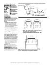
VALVES
The inlet valve should be in the full open position and the
discharge valve should be partially open, permitting some
back pressure to be exerted against the pump when starting
up. Open valve after start up is completed.
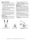
PRIMING
NOTE: Before starting the pump it is absolutely necessary
that both the pump and the inlet pipe be completely
filled with water.
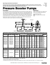
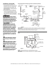
PRESSURE BOOST INSTALLATIONS
Priming is automatic when pump is connected to a pressure
source such as a hydrant or city main (See Figures 6, 7 & 8).
1. Open valves or nozzle on inlet and discharge side of pump.
2. To relieve trapped air, allow water supply to run a mini-
mum of 30 seconds before starting the pump.
IMPORTANT: An adequate flow of water going into the
pump is required so that the pumps impellers and shaft seal
do not run dry and fail.
3. If you installed a pressure gauge at the pump inlet, a read-
ing of 2 psi minimum should show whenever the pump is
in operation (See Figures 6, 7 & 8).
This reading insures that there is an ample supply of water
into the pump inlet housing.
IL0182
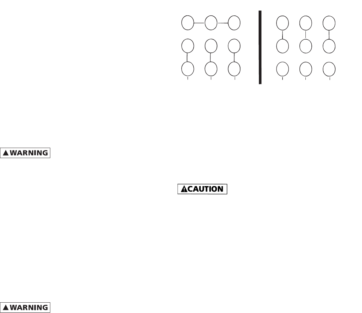
Low Voltage 230V High Voltage 460V
456
7
8
9
1
2
3
L
1
L
2
L
3
4
5
6
7
8
1
2
9
3
L
1
L
2
L
3
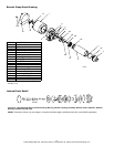
1 - Tan 4 - Yellow 7 - Purple
2 - Red 5 - Black 8 - Gray
3 - Orange 6 - Blue 9 - White
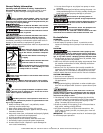
CONNECTION FOR 3 PHASE, 9 LEADS. IF YOUR 3 PHASE
LEADS ARE COLOR CODED, MATCH NUMBER ABOVE TO THE
CORRESPONDING COLOR.
NOTE: To reverse rotation, interchange any two incoming lines
(Power) leads.
Figure 11 - Wiring Diagram for Three Phase Motors