


24 Heatilator • GB4336/GB4992 • 4003-085 Rev H • 04/06
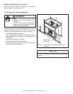
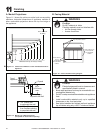
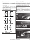
A. Mantel Projections
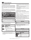
Figure 11.1 shows the minimum vertical and corresponding
maximum horizontal dimensions of appliance mantels or
other combustible projections above the top front edge of
the appliance.
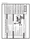
B. Facing Material
Measured from top of hood (in inches)
3 - 12
13
14
15
16
17
18
13-1/4
14
14-3/4
15-1/2
16-1/4
17
17-3/4
30 in. minimum
to ceiling
0 - 3
9-3/8
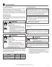
Figure 11.1 Clearances to Mantels or other Combustibles above
Appliance.
1 in. (25mm) min.
to perpendicular wall
A
3-1/2 in. (89 mm) min.
from fireplace opening
to perpendicular wall
B
48 in.
(1219 mm)
max.
Mantel Leg or
Perpendicular Wall
Top of
Appliance
Drywall
A
B
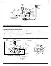
Figure 11.2 Mantel Leg or Wall Projections
(Acceptable on both sides of opening)
High temperature sealant
These surfaces may
be covered with
noncombustible
material
These surfaces
may be
covered with
noncombustible
material
Figure 11.3 Noncombustible Facing Diagram
11
11
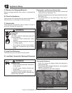
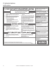
Finishing
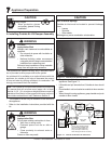
Fire Risk
Finish all edges and fronts to clearances and
specifi cations listed in manual.
WARNING
• Black metal appliance front may be covered with non-
combustible material only.
• Do NOT overlap combustible materials onto appliance
front.
• Install combustible materials only up to specifi ed
clearances on top, front and sides.
• Seal joints between the fi nished wall and appliance
top and sides using only a 300° F minimum sealant.
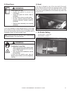
Fire Risk
Do NOT obstruct air inlets.
Finishing materials must not interfere with:
• Air fl ow through inlets.
• Access for service.
WARNING