


22 Heatilator • GB4336/GB4992 • 4003-085 Rev H • 04/06
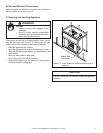
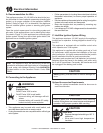
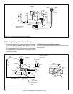
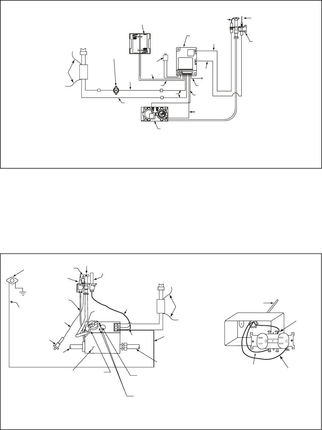
D. Standing Pilot Ignition System Wiring
• This standing pilot ignition system wiring does not require
a 110 VAC supply to operate. See Figure 10.3 for the
wiring diagram.
• It is recommended that a 110 VAC junction box be installed
for use with a fan or remote control. (See Figure 10.3 for
junction box wiring.)
Ignitor
Flame
Sensor
Pilot
GRN
ORG
BLK
ORG
Control
Box
To
Junction
Box
Battery
Pack
3V
Adapter
BLK
BRN
RED
RED
BLK
Valve
High
Limit
Switch
WHT
WALL SWITCH
WHT
GRN*
*
GRN wire only used with
optional wall switch
WSK-MLT-HTL
BLU
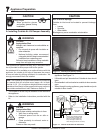
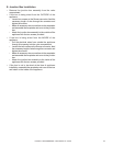
Figure 10.2 Intellifi re Pilot Ignition (IPI) Wiring Diagram
PILOT
IGNITOR
VARIABLE
FLAME
ADJUSTMENT
PILOT
ADJUSTMENT
CAP
ROBERTSHAW GAS
VALVE MODEL 7000
TO BURNER
GAS INLET
HIGH
LIMIT
SWITCH
BLK
ORG
TAN
BLK
PUSH
BUTTON
IGNITOR
TO
PILOT
TH
TP
TH/TP
THERMOPILE
FLAME
SENSOR
COPPER
TUBING
WALL SWITCH
BRN
INLET & OUTLET
PRESSURE
TAPS
RED
WHT
GRN*
* GRN wire only used with
optional wall switch
WSK-MLT-HTL
Figure 10.3 Standing Pilot Ignition Wiring Diagram
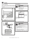
Optional Accessories Requirements
Wiring for optional accessories should be done now to avoid
reconstruction.
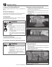
BLACK
WHITE
GROUND
14-2 with
Ground Romex
Optional Junction Box Wiring