


Heatilator • GB4336/GB4992 • 4003-085 Rev H • 04/06 19
A. Fuel Conversion
Before making gas connections ensure appliance being in-
stalled is compatible with the available gas type.
Any natural or propane gas conversions necessary to meet
the appliance and locality needs must be made by a quali-
fi ed technician using Hearth & Home Technologies specifi ed
and approved parts.
B. Gas Pressure
Proper input pressures are required for optimum appliance
performance. Gas line sizing requirements need to be made
following NFPA51.
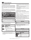
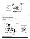
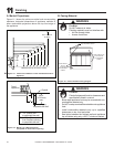
C. Gas Connection
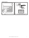
Refer to Reference Section 16 for location of gas line access
in appliance.
Note: Have the gas supply line installed in accordance
with local building codes, if any. If not, follow ANSI
223.1. Installation should be done by a qualifi ed installer
approved and/or licensed as required by the locality. (In
the Commonwealth of Massachusetts installation must be
performed by a licensed plumber or gas fi tter.)
Note: A listed (and Commonwealth of Massachusetts
approved) 1/2 in. (13 mm) T-handle manual shut-off valve
and fl exible gas connector are connected to the 1/2 in.
(13 mm) control valve inlet.
• If substituting for these components, please consult
local codes for compliance.
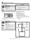
Pressure requirements for appliance are shown in table be-
low. Minimum pressures must be met when other household
gas appliances are operating.
Pressure Natural Gas Propane
Minimum Inlet Pressure 5.0 in. w.c. 11.0 in. w.c.
Maximum Inlet Pressure 7.0 in. w.c. 14.0 in. w.c.
Manifold Pressure 3.5 in. w.c. 10.0 in. w.c.
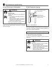
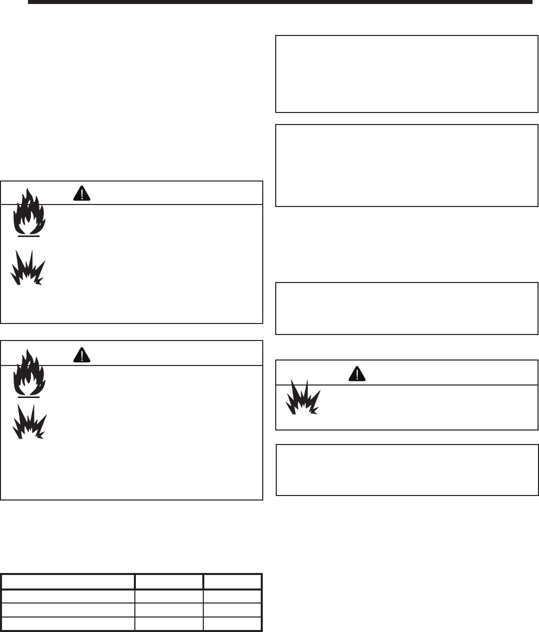
WARNING
Gas Leak Risk
• Support control when attaching pipe to
prevent bending gas line.
9
9
Gas Information
Fire Risk
Explosion Risk
High pressure will damage valve.
• Disconnect gas supply piping BEFORE
pressure testing gas line at test pressures
above 1/2 psig.
• Close the manual shutoff valve BEFORE
pressure testing gas line at test pressures
equal to or less than 1/2 psig.
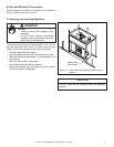
WARNING
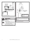
• Ensure that gas line does not come in contact with
outer wrap of appliance. Follow local codes.
• Incoming gas line should be piped into the valve
compartment and connected to the 1/2 in. connection
on the manual shutoff valve.
Note: Gas line may be run from either side of appliance
using one of the knockouts provided. Hole in outer shell
NOT to exceed 2-1/2 in. and should never penetrate the
fi r e b o x .
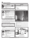
Fire Risk
Explosion Risk
Verify inlet pressures.
• High pressure may cause overfire
condition.
• Low pressure may cause explosion.
• Verify minimum pressures when other
household gas appliances are operating.
Install regulator upstream of valve if line
pressure is greater than 1/2 psig.
WARNING
Note: The gap between supply piping and gas access hole
may be caulked with high temperature caulk or stuffed
with non-combustible, unfaced insulation to prevent cold
air infi ltration.