


Heatilator • Caliber BV Series • 4040-262 • Rev M • 08/09 33
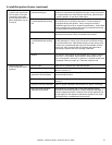
Symptom Possible Cause Corrective Action
1.
Pilot won’t light. The
ignitor/module makes
noise, but no spark.
A. Incorrect wiring. Verify “S” wire (white) for sensor and “I” wire (orange) for ignitor are
connected to correct terminals on module and pilot assembly.
B. Loose connections or electrical
shorts in the wiring.
Verify no loose connections or electrical shorts in wiring from module
to pilot assembly. Verify connections underneath pilot assembly are
tight; also verify connections are not grounding out to metal chassis,
pilot burner, pilot enclosure, mesh screen if present, or any other
metal object.
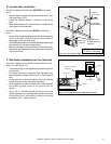
C. Ignitor gap is too large. Verify gap of igniter to right side of pilot hood. The gap should be
approximately .17 inch or 1/8 in. (3 mm).
D. Module. Turn ON/OFF rocker switch or wall switch to OFF position. Remove
ignitor wire “I” from module. Place a grounded wire about 3/16 in.
(5 mm) away from “I” terminal on module. Place ON/OFF rocker
switch or wall switch in ON position. If there is no spark at “I” terminal
module must be replaced. If there is a spark at “I” terminal, module
is ne. Inspect pilot assembly for shorted sparker wire or cracked
insulator around electrode. Replace pilot if necessary.
2. Pilot won’t light, there is no
noise or spark.
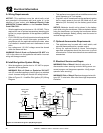
A. No power or transformer
installed incorrectly.
Verify that transformer is installed and plugged into module. Check
voltage of transformer under load at spade connection on module
with ON/OFF switch in ON position. Acceptable readings of a good
transformer are between 3.2 and 2.8 volts AC.
B. A shorted or loose connection
in wiring conguration or wiring
harness.
Remove and reinstall the wiring harness that plugs into module.
Verify there is a tight t. Verify pilot assembly wiring to module.
Remove and verify continuity of each wire in wiring harness.
Replace any damaged components.
C. Improper wall switch wiring. Verify that 110/VAC power is “ON” to junction box.
D. Module not grounded. Verify black ground wire from module wire harness is grounded to
metal chassis of appliance.
E. Module. Turn ON/OFF rocker switch or wall switch to OFF position. Remove
ignitor wire “I” from module. Place ON/OFF rocker switch or wall
switch in ON position. If there is no spark at “I” terminal module must
be replaced. If there is a spark at “I” terminal, module is ne. Inspect
pilot assembly for shorted sparker wire or cracked insulator around
electrode.
3. Pilot sparks, but Pilot will
not light.
A. Gas supply. Verify that incoming gas line ball valve is “open”. Verify that inlet
pressure reading is within acceptable limits.
B. Ignitor gap is incorrect. Verify that spark gap from ignitor to pilot hood is .17 in. or 1/8 in (3
mm).
C. Module is not grounded. Verify module is securely grounded to metal chassis of appliance.
D. Module voltage output / Valve/
Pilot solenoid ohms readings.
Verify battery voltage is at least 2.7 volts. Replace batteries if voltage
is below 2.7.
A. Intellire Ignition System (continued)
4. Pilot lights but continues
to spark, and main burner
will not ignite. (If the pilot
continues to spark after
the pilot ame has been lit,
ame rectication has not
occurred.)
A. A shorted or loose connection
in ame sensing rod.
Verify all connections to wiring diagram in manual. Verify
connections underneath pilot assembly are tight. Verify connections
are not grounding out to metal chassis, pilot burner, pilot enclosure
or screen if present, or any other metal object.
B. Poor ame rectication or
contaminated ame sensing
rod.
With xed glass assembly in place, verify that ame is engulng
ame sensing rod on left side of pilot hood. Flame sensing rod
should glow shortly after ignition. Verify correct pilot orice is
installed and gas inlet is set to pressure specications. Clean ame
sensing rod with emery cloth to remove any contaminants that may
have accumulated on ame sensing rod.
C. Module is not grounded. Verify module is securely grounded to metal chassis of appliance.
Verify that wire harness is rmly connected to the module.
D. Damaged pilot assembly or
contaminated ame sensing
rod.
Verify that ceramic insulator around the ame sensing rod is not
cracked, damaged, or loose. Verify connection from ame sensing
rod to white sensor wire. Clean ame sensing rod with emery cloth
to remove any contaminants that may have accumulated on ame
sensing rod. Verify continuity with a multimeter with ohms set at
lowest range. Replace pilot if any damage is detected.
E. Module. Turn ON/OFF rocker switch or wall switch to OFF position. Remove
ignitor wire “I” from module. Place ON/OFF rocker switch or wall
switch in ON position. If there is no spark at “I” terminal module must
be replaced. If there is a spark at “I” terminal, module is ne.
5. The pilot and main
burner extinguish while in
operation.
A. No LP in tank. Check the LP (propane) tank. Rell the fuel tank.
B. Improper gas inlet pressure. Verify with manometer. NG should read 5-14 inches w.c. LP should
read 10-14 inches w.c.
C. Inner vent pipe leaking exhaust
gases back into the system.
Check venting system for damage. Replace/repair improperly
assembled pipe sections.
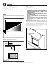
D. Glass installed improperly. Check to ensure glass is installed properly. Replace glass panel
assembly.
E. Improper vent cap installation. Check for proper installation and freedom from debris or blockage.
F. High limit switch has been
automatically activated.
This appliance is equipped with an auto reset high limit switch
which will shut down the appliance if it spills under ue blockage or
excessive negative pressure conditions. Shut off the appliance and
the gas supply. Do not attempt to operate the appliance until it has
been examined by a qualied service technician.