


Heatilator • Caliber BV Series • 4040-262 • Rev M • 08/09 25
A. Fuel Conversion
• Make sure the appliance is compatible with available
gas types.
• Conversions must be made by a qualified service
technician using Hearth & Home Technologies specied
and approved parts.
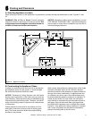
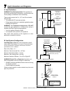
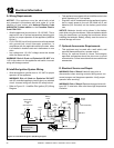
C. Gas Connection
• Refer to Reference Section 16.A. for location of gas line
access in appliance.
• Gas line may be run through knockout(s) provided on
either side or the bottom of the appliance.
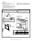
• The gap between supply piping and gas access hole
may be caulked with high temperature caulk or stuffed
with non-combustible, unfaced insulation to prevent cold
air inltration.
• Ensure that gas line does not come in contact with outer
wrap of the appliance. Follow local codes.
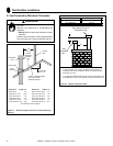
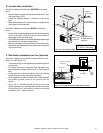
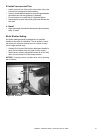
• Pipe incoming gas line into valve compartment.
• Connect incoming gas line to the 1/2 in. (13 mm)
connection on manual shutoff valve.
Support control
when attaching pipe to prevent bending gas line.
• A small amount of air will be in the gas supply lines.
Gas build-up dur-
ing line purge could ignite.
• Purge should be performed by qualified service
technician.
• Ensure adequate ventilation.
• Ensure there are no ignition sources such as sparks or
open ames.
Light the appliance. It will take a short time for air to purge
from lines. When purging is complete the appliance will
light and operate normally.
Check all ttings and connections with a non-corrosive
commercially available leak-check solution. use
open ame. Fittings and connections could have loos-
ened during shipping and handling.
change valve settings.
This valve has been preset at the factory.
High pressure
will damage valve. Low pressure may cause explosion.
• Verify inlet pressures. Verify minimum pressures when
other household gas appliances are operating.
• Install regulator upstream of valve if line pressure is
greater than 1/2 psig.
11
Gas Information
Gas Pressure Natural Gas Propane
Minimum inlet pressure 5.0 in. w.c. 11.0 in. w.c.
Maximum inlet pressure 10.0 in. w.c. 13.0 in. w.c.
Manifold pressure 3.5 in. w.c. 10.0 in. w.c.
Note: Have the gas supply line installed in accordance with local
codes, if any. If not, follow ANSI 223.1. Installation should be done
by a qualied installer approved and/or licensed as required by
the locality. (In the Commonwealth of Massachusetts installation
must be performed by a licensed plumber or gas tter).
Note: A listed (and Commonwealth of Massachusetts approved)
1/2 in. (13 mm) T-handle manual shut-off valve and exible gas
connector are connected to the 1/2 in. (13 mm) control valve
inlet.
• If substituting for these components, please consult
local codes for compliance.
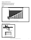
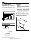
D. High Altitude Installations
If the heating value of the gas has been reduced,
these rules do not apply. Check with your local gas utility or
authorities having jurisdiction.
When installing above 2000 feet elevation:
• In the USA: Reduce burner orice 4% for each 1000 feet
above 2000 feet.
• In CANADA: Reduce burner orice 10% for elevations
between 2000 feet and 4500 feet. Above 4500 feet,
consult local gas utility.
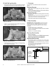
Fire Risk.
Explosion Hazard.
High pressure will damage valve.
• Disconnect gas supply piping BEFORE
pressure testing gas line at test pressures
above 1/2 psig.
• Close the manual shutoff valve BEFORE
pressure testing gas line at test pressures
equal to or less than 1/2 psig.
WARNING
B. Gas Pressure
• Optimum appliance performance requires proper input
pressures.
• Gas line sizing requirements will be determined in ANSI
Z221.3 National Fuel Gas Code in the USA and CAN/
CGA B149 in Canada.
• Pressure requirements are: