


Heatilator • Caliber BV Series • 4040-262 • Rev M • 08/09 27
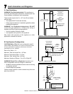
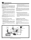
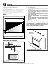
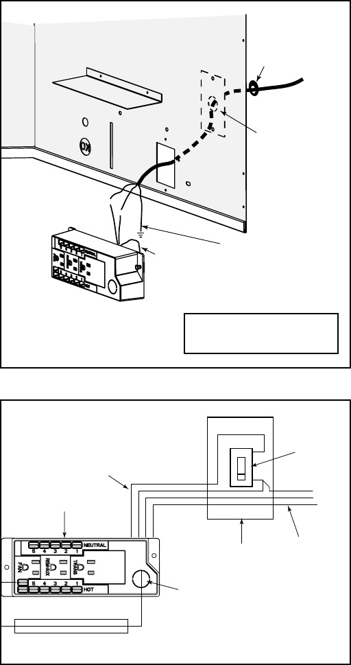
F. Wall Switch Installation for Fan (Optional)
If the box is being wired to a wall mounted switch for use
with a fan, see Figure 12.3:
• The power supply for the appliance must be brought into
a switch box.
• The power can then be supplied from the switch box
to the appliance using a minimum of 14-3 with ground
wire.
• At the switch box connect the black (hot) wire and red
(switch leg) wire to the wall switch as shown.
• At the appliance connect the black (hot), white (neutral)
and green (ground) wires to the junction box as
shown.
• Add a 1/4 in. insulated female connector to the red
(switch leg) wire, route it through the knockout in the face
of the junction box, and connect to the top fan switch
connector (1/4 in. male) as shown.
W
H
T
W
H
T
B
L
K
B
L
K
GRN wire
inside box
Copper
ground attached
to GRN screw with
GRN wire
14/2WG
Cover Plate
outside firebox
Romex
Connector
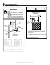
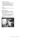
Figure 12.2 Junction Box Detail
wire
110 VAC to wall switch.
Red
Switch
Switch Box
Red
Black
Black
Green
Green
White
Power
Supply
Wires
White
Red
Black
Green
White
Minimum 14-3AWG
with Ground
Junction Box
Knockout
Figure 12.3 Junction Box Wired to Wall Switch or BC10
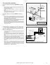
E. Junction Box Installation
If the box is being wired from the INSIDE of the appli-
ance:
• Remove the screw attaching the junction box/receptacle
to the outer shell, rotate the junction box inward to
disengage it from the outer shell.
• Pull the electrical wires from outside the appliance through
this opening into the valve compartment.
• Make all necessary wire connections to the junction box/
receptacle and reassemble the junction box/receptacle
to the outer shell.
If the box is being wired from the OUTSIDE of the appli-
ance:
• Remove the cover plate located on the outer shell - right
side (see Figure 12.2).
• Install the supplied Romex™ connector in the cover
plate.
• Make all necessary wire connections and reattach the
cover plate to the outer shell.