


5
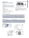
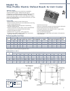
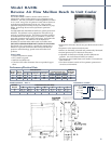
Model BTO
Twin Flow Reach In Unit Cooler
APPLICATION
Twin flow unit coolers are ideal for temperatures of 35°F and
higher. Box temperatures are kept more constant throughout
and fresh products last longer. Seven sizes are available with
BTUH from 900 to 5,500 at 10° TD. Larger BTO sizes are
suitable for large reach-in and small step-in or walk-in
coolers.
FEATURES
• Compact two-way design with medium velocity air flow.
• Mounts flush to the ceiling and draws air in through the fan
and discharges out both sides.
• Air pattern reduces air loss when doors are opened and the
medium velocity reduces product drying.
•Textured aluminum cabinet.
• Stainless steel fasteners.
• Molded Lexan
®
fan guards - safety approved.
• Drain pan and fan panel is easily removed for installation
and servicing.
• Coils are copper tube with aluminum fins.
• Expansion valve mounts inside the cabinet.
• Internal junction box is provided for electrical connection.
• Motors are thermally protected and permanently lubricated.
• UL listed for the United States and Canada; UL classified to
NSF standards.
• Optional corrosion-resistant coated coil available (Model
BTOK) for optimum protection in corrosive environments.
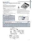
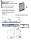
BTO(K) MOTOR DATA
MODEL BTUH 115/1/60 208-230/1/60
NO. 10
°
T.D. 15
°
T.D. CFM QTY
TOTAL FLA
TOTAL FLA
09 900 1350 130 1 0.8 0.4
13 1300 1950 240 2 1.6 0.8
18 1800 2700 255 1 1.0 0.5
25 2500 3750 460 2 2.0 1.0
35 3500 5250 425 2 2.0 1.0
45 4500 6750 550 2 2.0 1.0
55 5500 8250 730 1 2.1 1.1
Performance/Electrical Data
BTO K 09 A E
Vintage
A = 115/1/60
B = 208-230/1/60
BTO = Twin Flow
Unit Cooler
K = Coated Coil
(Optional)
Size
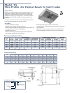
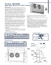
NOMENCLATURE
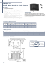
APPROX.
BTO(K) SHIP
MODEL CONNECTIONS (INCHES) DIMENSIONS (INCHES) WT.
NO. INLET SUCTION DRAIN A B C D E F G H J K L M (LBS.)
09
1
/2 FN
1
/2 ID
1
/2 OD 16
1
/8 19
1
/8 7
9
/16 42
5
/16 9
9
/16 2
3
/4 4
7
/8 4
1
/2 8
5
/8 2
1
/2 2
5
/8 12
13
1
/2 FN
1
/2 ID
1
/2 OD 16
1
/8 19
1
/8 7
9
/16 42
5
/16 9
9
/16 2
3
/4 5
3
/4 4
1
/2 8
5
/8 2
1
/2 2
5
/8 14
18
1
/2 FN
1
/2 ID
1
/2 OD 16
1
/8 19
1
/8 7
9
/16 42
5
/16 9
9
/16 2
3
/4 5
3
/4 4
1
/2 8
5
/8 2
1
/2 2
5
/8 15
25
1
/2 FN
1
/2 ID
1
/2 OD 18
1
/8 26
1
/8 11
1
/16 42
5
/16 13
1
/16 2
3
/4 6
3
/4 5
1
/2 12
1
/8 3
1
/2 2
5
/8 23
35
1
/2 FN
1
/2 ID
1
/2 OD 18
1
/8 26
1
/8 11
1
/16 42
5
/16 13
1
/16 2
3
/4 6
3
/4 5
1
/2 12
1
/8 3
1
/2 2
5
/8 24
45*
1
/2 FN
1
/2 ID
5
/8 OD 21
1
/8 29
1
/8 11
9
/16 63
7
/16 14
9
/16 3
1
/2 9
1
/4 813
5
/8 5
3
/8 4
1
/4 34
55*
1
/2 FN
1
/2 ID
5
/8 OD 21
1
/8 29
1
/8 11
9
/16 63
7
/16 14
9
/16 3
1
/2 8
1
/2 813
5
/8 5
3
/8 4
1
/4 34
* Sizes 45 and 55 use external equalized expansion valve.
DIMENSIONAL DATA