


Heat & Glo • SLR • 2143-900 Rev. B • 7/08 48
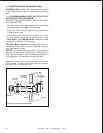
WARNING! Risk of Fire! Maintain specifi ed air space
clearances to combustibles.
Failure to comply with these instructions may cause a
fi re or cause the appliance to overheat.
Ensure that the one inch back clearance and one inch
side clearances are maintained.
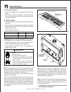
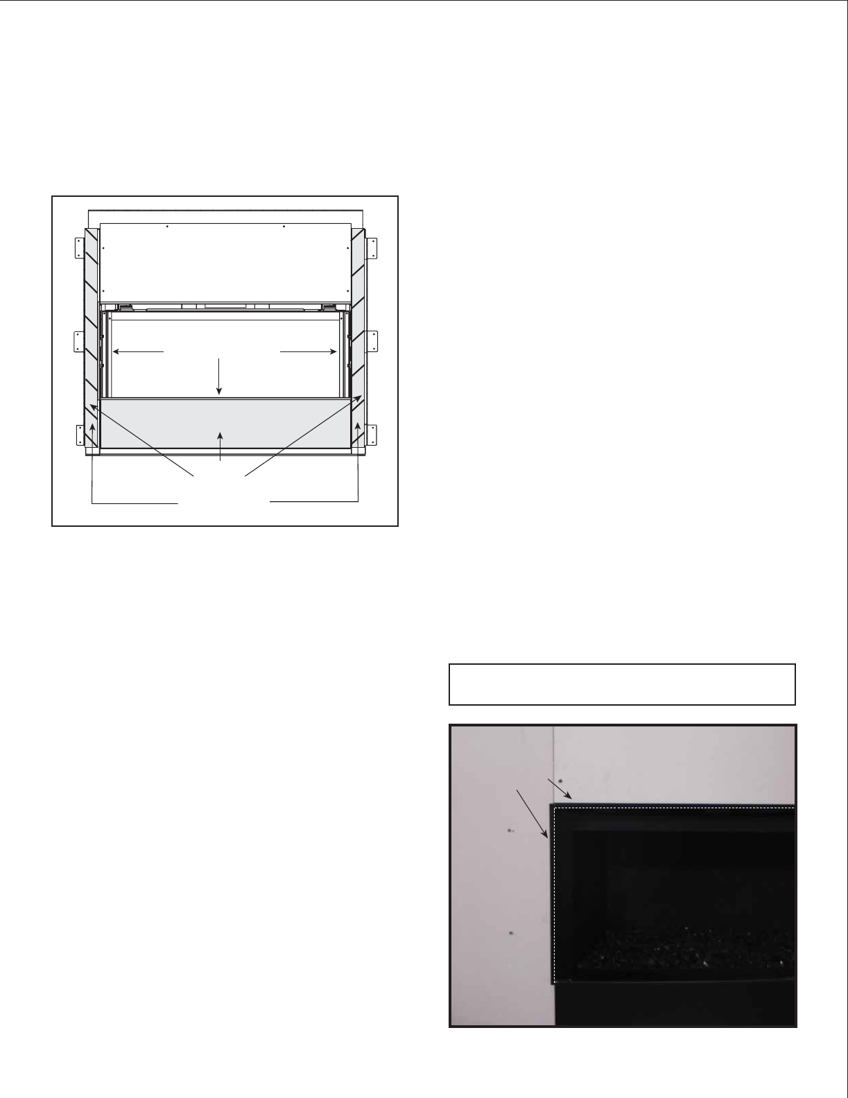
NON-COMBUSTIBLE BOARD
(PROVIDED WITH UNIT)
LOWER COVER PANEL
SIDE COLUMNS
NO
SCREWS
TOP FLANGE
FINISHING FLANGES
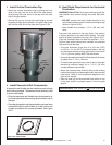
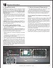
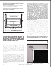
Figure 13.4 Finishing Details
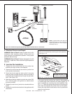
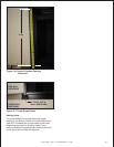
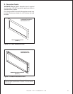
Figure 13.5 Side Wall Sheathing Installed
CAUTION! RISK OF GLASS DAMAGE AND CUTS! DO
NOT DRILL OR INSTALL ANY TYPE OF SCREW OR
FASTENER INTO THE LOWER COVER PANEL. SHARP
SCREW OR FASTENER TIPS MAY PENETRATE AND
BREAK THE GLASS OR CAUSE CUTS.
The SLR can be fi nished using either the Tonic or
Martini decorative fronts. See Figures 13.17 and 13.18.
Depending on the decorative front, the fi nal fi replace
installation can be accomplished by either the “overlap”
or “inside-fi t” method. Reference Section 13.C regarding
installation details associated with the Inside and Overlap
Fit methods.
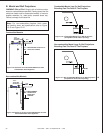
If the fi nal fi replace installation uses the Overlap Method,
wall sheathing material ½” thick is specifi ed and can
be installed tight to the side fi nishing fl anges. If the
fi nal fi replace installation uses the Inside-Fit Method,
additional clearance of 4” must be maintained between
combustible ½” thick wall sheathing material and the
side fi nishing fl anges. Reference Section 13.C regarding
installation details associated with the Inside and Overlap
Fit methods.
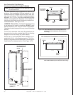
When fi nishing the wall around the fi replace, it is critical
that wall sheathing be fastened properly. Wall sheathing
fasteners, such as screws or nails, are not permitted in
some locations. See Figure 13.4. It is acceptable to
pre-drill holes and use self-tapped screws in the factory-
installed non-combustible board which may be used
to lathe (a backer for tile, marble, etc.) Screws being
installed through the factory-installed non-combustible
board should be self-tapping type with a minimum length
of 5” and maximum length of 7”. It is also acceptable
to penetrate the top fl ange with self-tapping screws.
See Figure 13.4. Do not drill or install screws into the
side columns as the existing stand-offs will support
the wall sheathing. Do not drill or install screws which
may penetrate the lower cover panel as this will restrict
required access to the glass, battery-back-up, and remote
receiver. See Figure 13.4.
The appliance is designed to accept ½” wall sheathing
materials such as drywall, plywood, wood composites,
or non-combustible materials. The type of material used
depends whether the installation is an Inside or Overlap
Fit method. Reference Section 13.C regarding installation
details associated with the Inside an Overlap Fit methods.
The left/right sides and bottom of the fi replace opening
include fi nishing fl anges that will interlock with ½” wall
sheathing. See Figure 13.4. The ½” thick wall sheathing
can be installed tight to the left, right, and bottom fi nishing
fl anges such that the rough edges of the sheathing
are tucked behind the fl anges. See Figure 13.5. It is
necessary to cut a ½” slot in the sheathing where it is
tucked tightly behind the lower fi nishing fl ange. See
Figure 13.7.
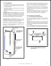
Verify that the lover cover panel is installed correctly, and
that the fi replace opening height is 16 in. See Figure 13.6.
NOTE: It is acceptable to use a high temperature sili-
cone sealant to adhere drywall to lower cover panel.
FINISHING
FLANGES
Î