


Heat & Glo • SLR • 2143-900 Rev. B • 7/08 43
A. Fuel Conversion
• Make sure the appliance is compatible with available gas
types.
• Conversions must be made by a qualified service
technician using Hearth & Home Technologies specifi ed
and approved parts.
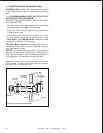
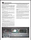
B. Gas Pressure
• Optimum appliance performance requires proper input
pressures.
• Gas line sizing requirements will be determined in ANSI
Z221.3 National Fuel Gas Code in the USA and CAN/
CGA B149 in Canada.
• Pressure requirements are:
WARNING! Risk of Fire or Explosion! High pressure
will damage valve. Low pressure may cause explosion.
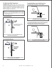
• Verify inlet pressures. Verify minimum pressures when
other household gas appliances are operating.
• Install regulator upstream of valve if line pressure is
greater than 1/2 psig.
11
11
Gas Information
Gas Pressure Natural Gas Propane
Minimum inlet pressure 5.0 in. w.c. 11.0 in. w.c.
Maximum inlet pressure 14.0 in. w.c. 14.0 in. w.c.
Manifold pressure 3.5 in. w.c. 10.0 in. w.c.
Note: Have the gas supply line installed in accordance with
local codes, if any. If not, follow ANSI 223.1. Installation
should be done by a qualifi ed installer approved and/or
licensed as required by the locality. (In the Commonwealth
of Massachusetts installation must be performed by a
licensed plumber or gas fi tter).
Fire Risk.
Explosion Hazard.
High pressure will damage valve.
• Disconnect gas supply piping BEFORE
pressure testing gas line at test pressures
above 1/2 psig.
• Close the manual shutoff valve BEFORE
pressure testing gas line at test pressures
equal to or less than 1/2 psig.
WARNING
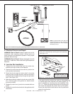
Note: A listed (and Commonwealth of Massachusetts ap-
proved) 1/2 in. (13 mm) T-handle manual shut-off valve
and fl exible gas connector are connected to the 1/2 in. (13
mm) control valve inlet.
• If substituting for these components, please consult
local codes for compliance.
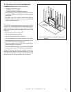
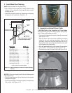
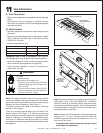
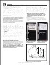
Note: This appliance does include a manual gas shutoff
valve that is located in the valve compartment. This manual
gas shutoff valve is accessible for service by removing the
basepan and burner assembly. See Figure 11.1.
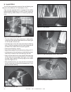
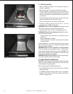
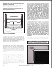
The lower access cover panel is removable if fi nishing
material is not installed.
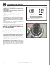
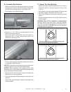
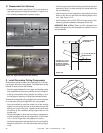
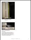
There is an access plate located on the left side of the
fi rebox bottom. See Figure 11.2. Remove screws and
plate to access the manual shutoff valve included with this
fi replace. See Figure 11.3 and Figure 11.4. Depending upon
local code, an additional manual gas shutoff, in an easily
accessible area may be required and located upstream from
the appliance.
ACCESS TO
MANUAL SHUTOFF
VALVE AND
JUNCTION BOX
VALVE
ASSEMBLY
LOWER COVER
PANEL
Figure 11.2 Gas and Electrical Access
SCREW LOCATIONS (16)
DO NOT REMOVE
THESE FOUR SCREWS
Figure 11.1 Basepan Removal
Î