


Heat & Glo • SLR • 2143-900 Rev. B • 7/08 45
FIREBOX BOTTOM
FIREBOX BOTTOM
A. Wiring Requirements
NOTICE: This appliance must be electrically wired
and grounded in accordance with local codes or, in the
absence of local codes, with National Electric Code
ANSI/NFPA 70-latest edition or the Canadian Electric
Code CSA C22.1.
• Wire the appliance junction box to 110-120 VAC. This is
required for use of optional accessories (standing pilot
ignition) or proper operation of the appliance (Intellifi re
ignition).
• Low voltage and 110 VAC voltage cannot be shared
within the same wall box.
WARNING! Risk of Shock or Explosion! DO NOT wire
110V to the valve or to the appliance wall switch. Incorrect
wiring will damage controls.
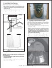
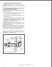
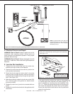
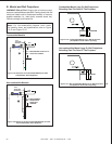
B. Intellifi re Ignition System Wiring
• Wire the appliance junction box to 110 VAC for proper
operation of the appliance.
WARNING! Risk of Shock or Explosion! DO NOT wire
IPI controlled appliance junction box to a switched circuit.
Incorrect wiring will override IPI safety lockout.
• Refer to Figure 12.2, Intellifi re Pilot Ignition (IPI) Wiring
Diagram.
• This appliance is equipped with an Intellifi re control valve
which operates on a 3 volt system.
• Plug the 3-volt AC transformer into the appliance junction
box to supply power to the unit OR install two D cell
batteries (not included) into the battery pack before use.
NOTICE: Batteries should not be placed in the battery
pack while using the transformer. Remove batteries before
using the transformer, and unplug the transformer before
installing the batteries. Battery polarity must be correct or
module damage will occur.
C. Optional Accessories Requirements
• This appliance may be used with a wall switch, wall
mounted thermostat and/or a remote control.
Wiring for optional Hearth & Home Technologies approved
accessories should be done now to avoid reconstruction.
Follow instructions that come with those accessories.
12
12
Electrical Information
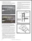
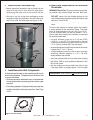
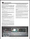
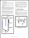
Optional Remote Control Receiver and Battery Pack
Location
Batteries are to be installed only when battery power is
required. Because of the limited accessibility to valve
cavity, the position of the Battery Tray, IPI Control Module,
and Optional Remote Control Receiver locations must be
installed as shown in Figure 12.1.
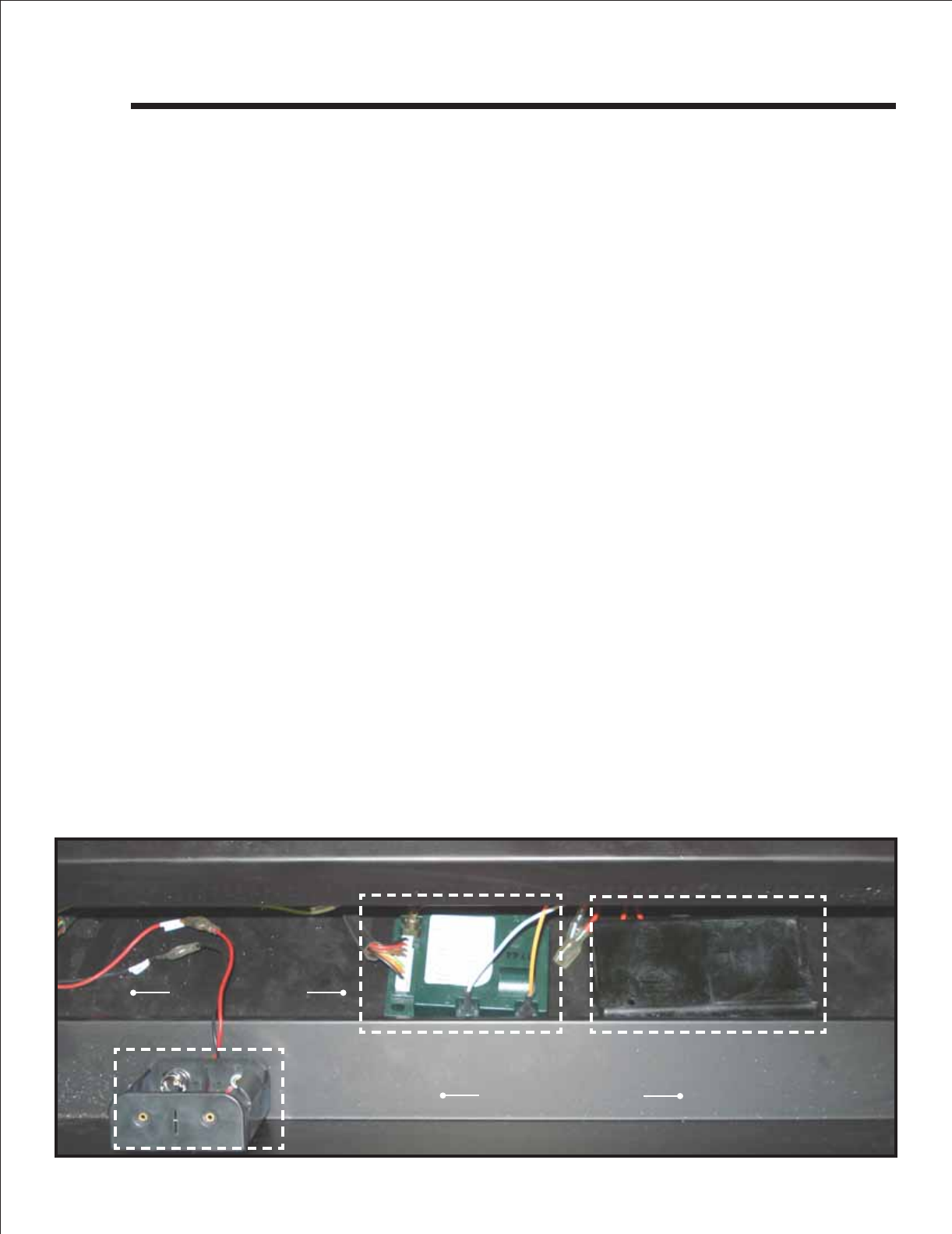
The Battery Tray, Control Module, and Remote Control
receiver can be accessed thru the air space between the
fi rebox front and the lower-front fi nishing cover panel. The
decorative front and glass assembly must be removed to
access these components.
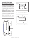
The battery tray is attached with velcro to the inside of
the lower cover panel. The IPI control module and the
remote control receiver are placed on the fi rebox bottom.
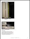
Figure 12.1 Valve Cavity
REMOTE CONTROL RECEIVER
IPI CONTROL MODULE
BATTERY TRAY
LOWER ACCESS PANEL
Î