


Heat & Glo • Crescent II • 2083-902 Rev. N • 7/0932
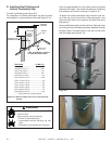
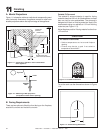
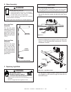
A. Mantel Projections
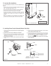
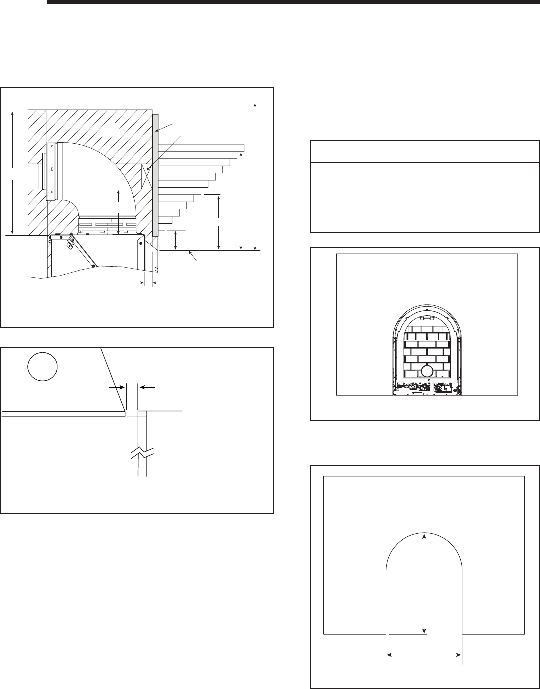
Figure 11.1 shows the minimum vertical and corresponding maxi-
mum horizontal dimensions of appliance mantels or other com-
bustible projections above the top front edge of the appliance.
11
11
Finishing
Figure 11.2 Mantel leg or Wall projections
(Acceptable on both sides of opening.)
Figure 11.1 Clearances to mantels or other combustibles
above appliance
Note: All measurements in inches.
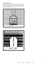
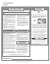
B. Facing Requirements
There are two options to fi nish the front facing on the fi replace,
outside fi t surround and inside fi t surround.
Figure 11.3 Outside Fit Surround
Outside Fit Surround
The outside fi t surround design is used for facing
materials less than 3/4 inch for combustibles, and less
than one inch for non-combustibles. The surround is
designed to fi t fl ush on fi nishing materials. Heat & Glo
recommends using our cabinets or 1/2 inch fi nishing
materials (see Figure 11.3).
Adjust fi replace position if facing material is other than
1/2 inch thick.
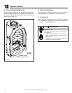
Figure 11.4 Outside Facing Dimensions
22-7/8 IN.
30-7/16 IN.
CAUTION
For Outside Fit Surrounds
• Surface temperatures are hot around fi replace
opening.
• Finishes may discolor or peel if not suited to
temperatures above 200º
F.
½ Inch
MANTEL
LEG
Top View
6-5/16 IN.
2-3/4 IN.
1 in.
1
2
3
4
5
6
7
8
9
10
11
12
7-3/4 IN.
27 IN.
FROM BOTTOM OF HOOD
(VISIBLE WITH DOOR REMOVED)
COMBUSTIBLE
SHEATHING
HEADER BOARD
16-1/4 IN.
AIR
SPACE
13-3/4 IN.
CEILING
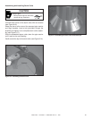
To cut the arch use the dimensions shown in Figure
11.4.