


Heat & Glo • Cerona-36, Cerona-42 • 2106-900 Rev. A • 6/06
18
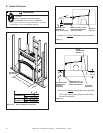
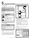
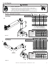
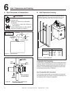
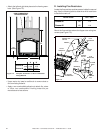
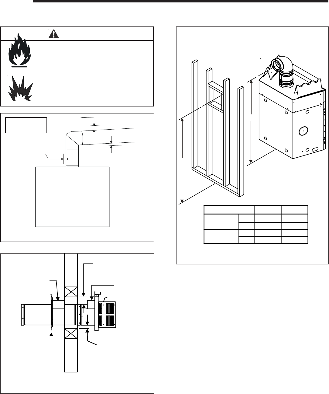
A. Pipe Clearances to Combustibles
Vent Clearances and Framing
6
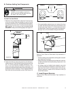
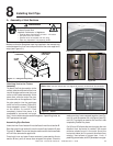
Combustible Wall Penetration
Frame a hole in a combustible wall for an interior wall shield
firestop, (Figure 6.2) whenever a wall is penetrated. Use
same size framing materials as those used in the wall con-
struction. The wall shield firestop maintains minimum clear-
ances and prevents cold air infiltration.
Non-Combustible Wall Penetration
If the hole being penetrated is surrounded by noncombusti-
ble materials such as concrete, a hole with diameter one
inch greater than the pipe is acceptable.
Fire Risk.
Explosion Risk.
Maintain vent clearance to combustibles
as specified.
WARNING
• Do not pack air space with insulation or
other materials.
Failure to keep insulation or other materials
away from vent pipe may cause fire.
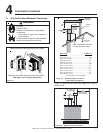
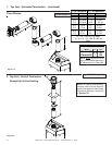
B. Wall Penetration Framing
Figure 6.1 Pipe Clearances
1 in. CLEARANCE
AROUND VERTICAL
SECTIONS
3 in. TOP
CLEARANCE
1 in. SIDE AND
BOTTOM CLEARANCE
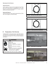
Figure 6.2 Exterior Wall Hole
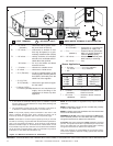
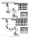
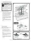
Figure 6.2 Horizontal Venting Clearances to
Combustible Materials
NOTE: Slope
not required.
Shows center of 10 inch x 12 inch vent framing holes for
top and rear venting. The center of the hole is one (1) inch
(25.4mm) above the center of the horizontal vent pipe.
WALL
HEAT
SHIELD
HEAT
SHIELD
3 in. TOP
CLEARANCE
WALL
SHIELD
FIRESTOP
1 in. CLEARANCE
BOTTOM & SIDES
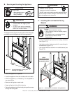
A
B
AB
Cerona-36
in. 61-1/2 60-1/2
mm 1562 1537
Cerona-42
in. 72 71
mm 1829 1803