


28
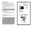
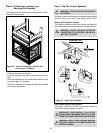
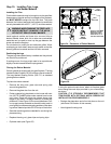
For Direct Spark Ignition (DSI) Wiring
Appliance Requirements
This appliance requires that 110-120 VAC be wired to the
factory installed junction box. Maintain correct polarity when
wiring the junction box.
Optional Accessories
Optional fan and remote control kits require that 110-120
VAC be wired to the fireplace junction box.
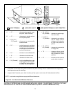
FLAME SENSOR/SPARKER
IGNITION
MODULE
GAS
VALVE
ON/OFF SWITCH
REMOTE OUTLET
FAN OUTLET
CONNECTORS
HOT
GROUND
NEUTRAL
OPTIONAL REMOTE,
WALL SWITCH
OR THERMOSTAT
(ON CERTIFIED UNITS ONLY)
BLACK
GROUND
FAN
REM
OPTIONAL
FAN
SWITCHES
L2
(NEUTRAL)
L1
(HOT)
100-254A
JUNCTION
BOX
120 VAC
ON/OFF
120 VAC
POWER CORD
GROUND
TO
FIREPLACE
CHASSIS
WHITE
GREEN
BLUE
501-592
DSI
MODULE
ORANGE
459-591
IGNITOR
476-500
DSI CONTROL VALVE
BLUE
WHITE
WHITE
BLACK
WHITE
YELLOW
BLUE
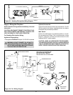
Figure 31. Direct Spark Ignition Wiring Diagram
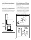
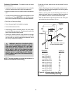
Wall Switch
Position the wall switch in the desired position on a wall.
Run a maximum of 25 feet (7.8 m) or less of 16 A.W.G.
minimum wire and connect it to the fireplace ON/OFF switch
pigtails.
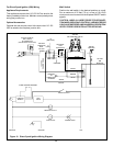
CAUTION: LABEL ALL WIRES PRIOR TO DISCONNEC-
TION WHEN SERVICING CONTROLS. WIRING ERRORS
CAN CAUSE IMPROPER AND DANGEROUS OPERATION.
VERIFY PROPER OPERATION AFTER SERVICING.