


19
B. Installing Vent Components
!
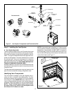
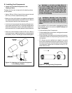
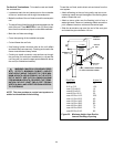
WARNING: A 3/8 INCH (9.5 MM) BEAD OF
STOVE CEMENT MUST BE PLACED AROUND
THE 4 INCH (102 MM) FIREPLACE STARTING COL-
LAR BEFORE ATTACHING THE FIRST VENT COM-
PONENT. FAILURE TO SEAL THIS JOINT MAY
CAUSE THE FIREPLACE TO OPERATE IMPROPER-
LY. SEE THE DIAGRAM .
STARTING
COLLAR
STOVE
SEALANT
BEAD
1 INCH
(25.4mm)
FIRST VENT
COMPONENT
!
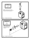
WARNING: ENSURE THAT THE FIBER-
GLASS ROPE GASKET SUPPLIED WITH
THE FIREPLACE SEALS BETWEEN THE FIRST
VENT COMPONENT AND THE OUTER FIREPLACE
WRAP.
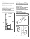
If the installation is for a termination cap attached directly
to the fireplace, skip to the sections, Install Firestops and
Vent Termination.
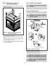
1. Attach the First Vent Component to the
Starting Collars
To attach the first vent component to the starting collars
of the fireplace:
Apply a 3/8 inch (9.5mm) bead of stove cement around
the 4 inch (102mm) fireplace starting collar.
Make sure that the fireplace rope gasket supplied with
the fireplace seals between the first 6-5/8 inch (168mm)
vent component and the outer fireplace wrap.
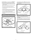
Lock the vent components into place by sliding the con-
centric pipe sections with four (4) equally spaced interior
beads into the fireplace collar or previously installed com-
ponent end with four (4) equally spaced indented sections.
When the internal beads of each 6-5/8 inch (168mm)
outer pipe line up, rotate the pipe section clockwise about
one-quarter (1/4) turn. The vent pipe is now locked together.
Figure 15. Attaching the First Vent Component
to the Starting Collars
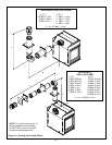
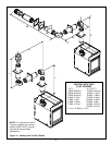
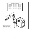
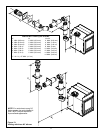
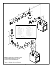
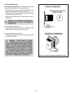
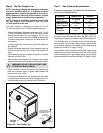
2. Continue Adding Vent Components
Continue adding vent components, locking each succeed-
ing component into place.
Ensure that each succeeding vent component is secure-
ly fitted and locked into the preceding component in the
vent system.
90° elbows may be installed and rotated to any point
around the preceding components vertical axis. If an el-
bow does not end up in a locked position with the preced-
ing component, attach with a minimum of two (2) 1/2
sheet metal screws.
Figure 16. Adding Venting Components