


10
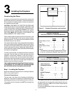
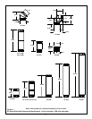
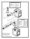
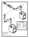
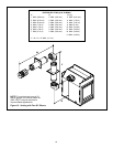
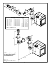
Figure 4. Vertical and Horizontal Vent Runs
28 15/16”
(734mm)
1” (25mm)
PIPE CLEARANCE
4
”
(
1
0
2
m
m
)
Vertical Vent Run
s
26 7/16”
(671mm)
Horizontal Vent Runs
1 1/2”
(38mm)
FIRESTOP
36 1/8”
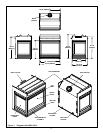
Framing should be constructed of 2 X 4 lumber or heavier.
Figure 3. Framing Dimensions
Shows center of 10 x 10 vent framing hole. The center of the
hole is one inch (25.4mm) above the center of the hori-
zontal vent pipe.
37 1/8”
(943mm)
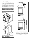
Step 2. Framing the Fireplace
Fireplace framing can be built before or after the fireplace is
set in place. Framing should be positioned to accommo-
date wall coverings and fireplace facing material. The dia-
gram below shows framing reference dimensions.
CAUTION: MEASURE FIREPLACE DIMENSIONS AND
VERIFY FRAMING METHODS AND WALL COVERING
DETAILS BEFORE FRAMING.
!
WARNING: FRAMING DIMENSIONS ASSUME
USE OF 1/2 INCH THICK WALL COVERING MA-
TERIALS ON EXTERIOR OF FRAMING ONLY
AND NO SHEETROCK ON INTERIOR OF FRAMING.
4A.
4B.
38 3/4
(984mm)
24 3/4
(62mm)
32 3/4
(831mm)
*
* This dimension may need to be adjusted depending on the
venting configuration. See Figure 4 for details. For vertical
runs inside wall per Figure 4A, add 4 inches. For horizontal
clearance to firestop per Figure 4B, add 1-1/2 inches.