


Heat & Glo • Escape-36DV • 2012-900 • Rev. AA • 04-08 33
11
11
Finishing
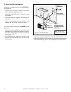
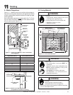
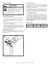
A. Mantel Projections
Figure 11.1 shows the minimum vertical and correspond-
ing maximum horizontal dimensions of appliance mantels
or other combustible projections above the opening edge
of the appliance.
Non-combustible materials must be used in the 7-1/2 inch
zone on each side and in the 10 inch zone above the ap-
pliance opening (see Figure 11.3).
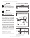
B. Facing Material
Risk of Fire
• Non-combustible clearances MUST be
maintained.
• Sheetrock, wood or other combustibles must
NOT be used as sheathing or facing in the
non-combustible zone.
• See Section 11 for proper clearances.
• See Section 1 for combustible/non-
combustible defi nitions.
WARNING
WARNING
NON-COMBUSTIBLE
MATERIAL
7-1/2 IN.
MINIMUM
UNLIMITED
Figure 11.3 Non-combustible Zone
Figure 11.2 Mantel Leg or Wall Projections
(Acceptable on both sides of opening.)
Figure 11.1 Clearances to Mantels or other Combustibles
above Appliance
Fire Risk.
• Facing and/or fi nishing material must never
overhang into the glass opening.
Finishing materials must not interfere with:
• Operation of louvers or doors.
• Access for service.
METAL PANELS
BEHIND NON-COMBUSTIBLE MATERIAL
NON-COMBUSTIBLE
FACING MATERIAL
54 IN.
41 IN.
MIN.
10 IN.
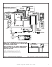
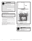
Fire Risk.
Hearth extension required to protect
combustible fl oors in front of appliance.
• An 12 inch minimum hearth extension must be constructed
of non-combustible material.
WARNING
8 IN.
12 IN.
COMBUSTIBLE
PROJECTIONS
METAL PANELS
(PROVIDED)
COMBUSTIBLE
FRAMING
11-1/2 IN.
12
10-1/2
9
7-1/2
6
4-3/4
2-1/4
1
36 IN.
3-1/2 IN.
4 IN.
MINIMUM
TOP OF
FIREPLACE
OPENING
NON-COMBUSTIBLE
MINIMUM NCH THICKNESS
FACING
1/2 I
NO COMBUSTIBLES
IN THIS AREA
FINISH WALL
COMBUSTIBLE
3-1/2
10 IN.
MINIMUM
Height Above Opening Horizontal Mantel Distance
4 in. 1 in.
5 in. 2-1/4 in.
6 in. 3-1/2 in.
7 in. 4-3/4 in.
8 in. 6 in.
9 in. 7-1/2 in.
10 in. 9 in.
11 in. 10-1/2 in.
12 in. 12 in.