


Heat & Glo • Escape-36DV • 2012-900 • Rev. AA • 04/0830
A. Recommendation for Wire
This appliance requires 110-120 VAC be wired to the
junction box for proper operation of the appliance
(Intellifi re ignition).
10
10
Electrical Information
Note: This appliance must be electrically wired and grounded
in accordance with local codes or, in the absence of local
codes, with National Electric Code ANSI/NFPA 70-latest
edition or the Canadian Electric Code, CSA C221.1.
B. Connecting to the Appliance
Wire 110V to electrical junction box.
Do NOT wire 110V to valve.
Do NOT wire 110V to wall switch.
• Incorrect wiring will damage millivolt valves.
• Incorrect wiring will override IPI safety lockout
and may cause explosion.
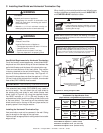
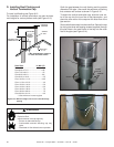
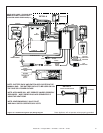
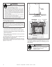
C. Intellifi re Ignition System Wiring
This appliance requires a 110 VAC supply to the appliance
junction box for operation. A wiring diagram is shown in
Figure 10.1.
This appliance is equipped with an Intellifi re control valve
which operates on a 3 volt system.
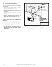
This appliance is supplied with a battery pack and a 3 volt
AC transformer, which requires the installation of the sup-
plied junction box. It is highly recommended that the junc-
tion box be installed at this time to avoid reconstruction.
The battery pack requires two D cell batteries (not includ-
ed). Batteries cannot be placed in the battery pack while
using the 3 volt transformer. Batteries shouldn’t be placed
into the holder until needed. The higher temperatures will
shorten their life.
CAUTION
Battery polarity must be correct or module damage will
occur.
Optional Accessories Requirements
Wiring for optional accessories should be done now to
avoid reconstruction. Heat-Zone kits are approved with this
appliance as heat management accessories.
• Use the wire provided with this product to connect the
wall switch to the receiver, as outlined in the WSK-MLT
instructions.
• Keep wire lengths short as possible by removing any
excess wire length.
• Low voltage and 110 VAC voltage cannot be shared
within the same wall box.
WARNING
CAUTION
Label all wires prior to disconnection when servicing controls.
Wiring errors can cause improper and dangerous operation.
Verify proper operation after servicing.
Shock hazard.
• Replace damaged wire with type 105º C rated
wire.
• Wire must have high temperature insulation.
WARNING
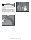
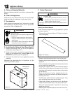
Wall Switch
This appliance comes standard with a multi-function wall
switch installed in the unit. A bag containing the wall
switch, cover plate and fl ame control solenoid is located
in the manual bag assembly on the right side of unit. Fol-
low the “Determine Location” and “Wiring the Wall Switch”
sections of the WSK-MLT instructions. Install the fl ame
control solenoid by following Steps 5 - 11 in the “Install-
ing the Control Box” section of the WSK-MLT instructions.
You must also carefully follow the “Setting Flame Height/
Manifold Pressure” section of the included instructions to
properly set the valve pressure. Operating instructions
are also included in the WSK-MLT instructions.
CAUTION
Remove refractory panels and mesh when operating
appliance using the battery pack or damage to components
may occur.
Use battery pack to operate appliance only in a power failure
situation.