


7
Heat & Glo • Soho24B • 2137-900 Rev. P • 8/12
B
C
A
A
1/2 IN.
ALCOVE
INSTALLATION
TOP VENT,
ONE 90º ELBOW
B
D
E
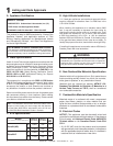
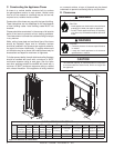
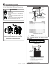
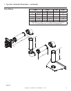
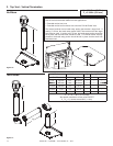
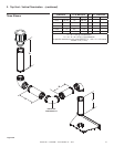
Figure 3.1 Appliance Locations
ABCDE
Inches 33-1/8 29-1/8 46-3/4 35-1/8 12
Millimeters 841 740 1187 892 305
In addition to these framing dimensions, also reference the following sections:
• Clearances and Mantel Projections (Section 3B).
• Vent Clearances and Framing (Section 6).
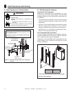
B. Mantel Projections
A Studio front is required for all installs. No mantels are
allowed when using Studio fronts.
3
3
Framing and Clearances
Note:
• Illustrations reflect typical installations and are FOR
DESIGN PURPOSES ONLY.
• Illustrations/diagrams are not drawn to scale.
• Actual installation may vary due to individual design
preference.
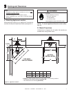
Fire Risk
Provide adequate clearance:
• Around air openings
• To combustibles
• For service access
Locate appliance away from traffi c areas.
A. Selecting Appliance Location
When selecting a location for your appliance it is important to
consider the required clearances to walls (see fi gure 3.1).
NOTE: For actual appliance dimensions refer to Sec-
tion 16.
WARNING