


31
Heat & Glo • Soho24B • 2137-900 Rev. P • 8/12
PLUG-IN
3V TRANSFORMER
ON/OFF
WALL SWITCH
IGNITION
MODULE
(3V)
VALVE
NEUTRAL
GROUND
LOWVOLTAGE
SEE NOTE 1
REMOTE
CONTROL HOT
PLUG-IN
REMOTE
JUMPERWIRE
ORG
GRN
BRN
BRN
RED
BLK
INTERMITTENT
PILOT IGNITOR
ORG
WHT
IGNITION MODULE 3 VAC
TRANSFORMER
VALVE
3 VAC
THERMOSTAT
WIRE
ASSEMBLY
BLACKWIRECAN BE
PLUGGEDINTOANY
OF #1 - #5 LOCATIONS
ON THE HOTSIDE
WHITEWIRE CAN BE
PLUGGED INTO ANY
OF#1 - #5LOCATIONS
ONTHE NEUTRALSIDE
GROUNDTO
FIREPLACE
CHASSIS*
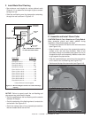
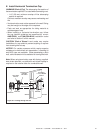
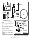
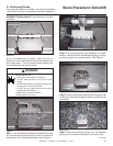
Figure 10.1 IntelliFire Pilot Ignition (IPI) Wiring Diagram - Standard Method. Note: Appliance will not operate unless properly grounded.
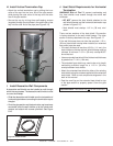
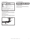
D. Junction Box Installation
If the box is being wired from the OUTSIDE of the
appliance:
• Remove the cover plate located on the outer shell
- right side (see Figure 10.2).
• Install the supplied Romex™ connector in the cover
plate.
• Feed the necessary length of wire through the
connector.
• Make all necessary wire connections and reattach
the cover plate to the outer shell.
If the box is being wired from the INSIDE of the
appliance:
• Remove the screw attaching the junction box/
receptacle to the outer shell, rotate the junction
box inward to disengage it from the outer shell (see
Figure 10.2).
• Pull the electrical wires from outside the appliance
through this opening into the valve compartment.
• Feed the necessary length of wire through the connector.
• Make all necessary wire connections to the junction box/
receptacle and reassemble the junction box/receptacle to the
outer shell.
WHT
WHT
BLK
BLK
GRN wire
inside box
Copper
ground attached
to GRN screw with
GRN wire
14/2WG
Cover Plate
outside firebox
Romex
Connector
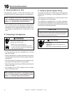
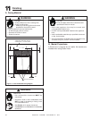
Figure 10.2 Junction Box Detail
NOTE: Do NOT wire
110VAC to wall switch.