


9
The Quality Leader in Conditioning Air
Residential Split - 60Hz R22 &R410A
Rev.: 5 June, 2008
www.heatcontoller.com
Installation
NOTICE! Failure to remove shipping
brackets from spring-mounted compressors
will cause excessive noise, and could cause
component failure due to added vibration.
The installation of water source heat pump units and all
associated components, parts and accessories which make
up the installation shall be in accordance with the regulations
of ALL authorities having jurisdiction and MUST conform to
all applicable codes. It is the responsibility of the installing
contractor to determine and comply with ALL applicable
codes and regulations.
Removing Existing Condensing Unit (Where Applicable)
1. Pump down condensing unit. Close the liquid line service
valve of existing condensing unit and start compressor
to pump refrigerant back into compressor section. Then,
close suction service valve while compressor is still
running to trap refrigerant in outdoor section. Immediately
kill power to the condensing unit.
2. Disconnect power and low voltage and remove old
condensing unit. Cut or unbraze line set from unit.
Remove condensing unit.
3. If condensing unit is not operational or will not pump
down, refrigerant should be recovered using appropriate
equipment.
4. Replace line set, especially if upgrading system from
R-22 to R-410A refrigerant. If line set cannot be replaced,
it must be thoroughly flushed before installing new
compressor section. R-410A compressors use POE
oil instead of mineral oil (R-22 systems). Mineral oil is
not compatible with POE oil, and could cause system
damage if not completely flushed from the line set.
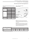
“Indoor” Compressor Section Location
Both “indoor” and “outdoor” versions of the geothermal split
system compressor section are available. “Indoor” version
is not designed for outdoor installation. Locate the unit in
an INDOOR area that allows enough space for service
personnel to perform typical maintenance or repairs without
removing unit. Units are typically installed in a mechanical
room or closet. Never install units in areas subject to freezing
or where humidity levels could cause cabinet condensation
(such as unconditioned spaces subject to 100% outside air).
Consideration should be given to access for easy removal
of service access panels. Provide sufficient room to make
water, electrical, and line set connections.
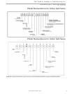
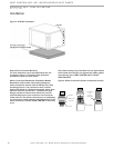
Any access panel screws that would be difficult to remove
after the unit is installed should be removed prior to setting the
unit. Refer to Figure 2 for an illustration of a typical installation.
Refer to “Physical Dimensions” section for dimensional data.
Conform to the following guidelines when selecting unit
location:
1.
Install the unit on a piece of rubber, neoprene or other
mounting pad material for sound isolation. The pad should
be at least 3/8” [10mm] to 1/2” [13mm] in thickness. Extend
the pad beyond all four edges of the unit.
2. Provide adequate clearance for maintenance and
service. Do not block access panels with piping, conduit
or other materials.
3. Provide access for servicing the compressor and coils
without removing the unit.
4. Provide an unobstructed path to the unit within the closet
or mechanical room. Space should be sufficient to allow
removal of the unit, if necessary.
5.
In limited side access installations, pre-removal of the
control box side mounting screws will allow control box
removal for future servicing (R22 units only).
6. Provide access to water valves and fittings and
screwdriver access to the unit side panels and all
electrical connections.
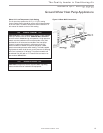
Air Handler Installation
This manual specifically addresses the compressor section
of the system. Air handler location and installation should be
according to the instructions provided with the air handling
unit.