


25
The Quality Leader in Conditioning Air
Residential Split - 60Hz R22 &R410A
Rev.: 5 June, 2008
www.heatcontoller.com
Electrical - Line Voltage
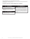
WARNING! To avoid possible injury or death due to
electrical shock, open the power supply disconnect switch
and secure it in an open position during installation.
CAUTION!
Use only copper conductors for eld installed
electrical wiring. Unit terminals are not designed to accept other
types of conductors.
x WARNING! x
x CAUTION! x
Electrical - Line Voltage
All eld installed wiring, including electrical ground, must comply
with the National Electrical Code as well as all applicable local
codes. Refer to the unit electrical data for fuse sizes. Consult
wiring diagram for eld connections that must be made by the
installing (or electrical) contractor.
All nal electrical connections must be made with a length of
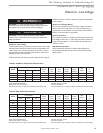
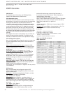
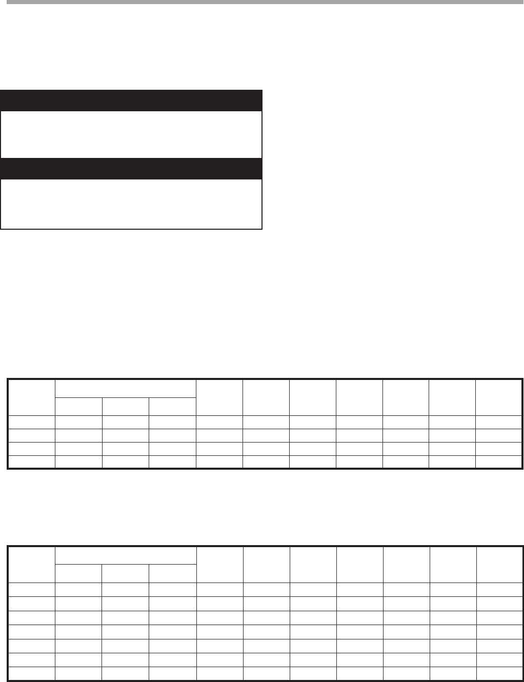
Table 8a: GeoMax 2 (HTS) Series Electrical Data
Table 8b: HSS Series Electrical Data
Model
Compressor
HWG
Pump
FLA
External
Pump
FLA
Total
Unit
FLA
Min
Circuit
Amps
Max
Fuse/
HACR
Min
AWG
Max Wire
Ft.
(m)
RLA LRA Qty
024 10.3 52.0 1 0.4 4.0 14.7 17.3 25 10 107 (32.7)
036 16.7 82.0 1 0.4 4.0 21.1 25.3 40 10 73 (22.3)
048 21.2 96.0 1 0.4 4.0 25.6 30.9 50 8 95 (29.2)
060 25.6 118.0 1 0.4 4.0 30.0 36.4 60 8 81 (24.8)
Rated Voltage of 208/230/60/1 Min/Max Voltage of 197/254
HACR circuit breaker in USA only All fuses Class RK-5
Wire length based on one way measurement with 2% voltage drop Wire size based on 60°C copper conductor and Minimum Circuit Ampacity.
Rated Voltage of 208/230/60/1 Min/Max Voltage of 197/254
HACR circuit breaker in USA only All fuses Class RK-5
Wire length based on one way measurement with 2% voltage drop Wire size based on 60°C copper conductor and Minimum Circuit Ampacity.
Model
Compressor
HWG
Pump
FLA
External
Pump
FLA
Total
Unit
FLA
Min
Circuit
Amps
Max
Fuse/
HACR
Min
AWG
Max Wire
Ft
(m)
RLA LRA Qty
018
7.7 40.3 1 0.40 4.0 12.1 14.0 20 12 76 (23.3)
024
10.3 56.0 1 0.40 4.0 14.7 17.3 25 10 107 (32.7)
030
12.2 67.0 1 0.40 4.0 16.6 19.7 30 10 94 (28.7)
036
13.5 73.0 1 0.40 4.0 17.9 21.3 35 10 87 (26.5)
042
16.5 95.0 1 0.40 4.0 20.9 25.0 40 10 74 (22.6)
048
18.3 109.0 1 0.40 4.0 22.7 27.3 45 10 67 (20.7)
060
25.0 148.0 1 0.40 4.0 29.4 35.7 60 8 82 (25.2)
exible conduit to minimize vibration and sound transmission
to the building.
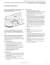
General Line Voltage Wiring
Be sure the available power is the same voltage and phase
shown on the unit serial plate. Line and low voltage wiring
must be done in accordance with local codes or the National
Electric Code, whichever is applicable.
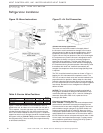
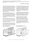
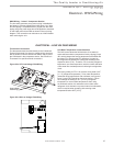
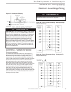
Power Connection
Line voltage connection is made by connecting the incoming
line voltage wires to the “L” side of the contactor as shown in
Figures 21a through 21c. Consult Tables 8a through 8c for
correct fuse size.
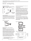
208-230 Volt Operation
Verify transformer tap with air handler wiring diagram to
insure that the transformer tap is set to the correct voltage,
208V or 230V.