


HEAT CONTROLLER, INC. WATER-SOURCE HEAT PUMPS
Residential Split - 60Hz R22 &R410A
Rev.: 5 June, 2008
20
Heat Controller, Inc. Water-Source Heating and Cooling Systems
Refrigeration Installation
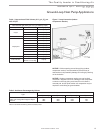
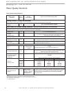
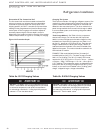
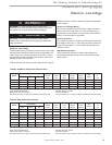
Table 6a: R-22 Charging Values
Table 6b: R-410A Charging Values
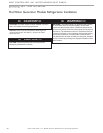
x NOTICE! x
NOTICE: Use tables 14a to 15 for superheat/subcooling
values. These tables use discharge pressure (converted
to saturation temperature) and liquid line temperature
for subcooling calculations. If using liquid line pressure,
subtract 3°F from the table values.
x NOTICE! x
NOTICE: Use tables 14a to 15 for superheat/subcooling
values. These tables use discharge pressure (converted
to saturation temperature) and liquid line temperature
for subcooling calculations. If using liquid line pressure,
subtract 3°F from the table values.
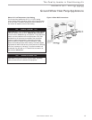
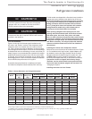
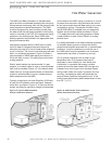
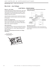
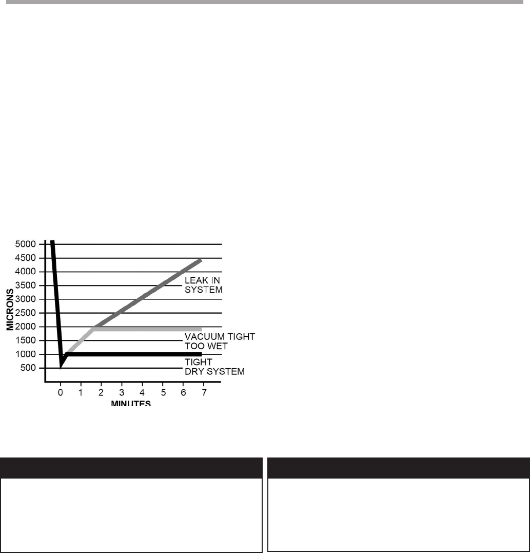
Evacuation Of The Lineset And Coil
The line set and coil must be evacuated to at least 500
microns to remove any moisture and noncondensables.
Evacuate the system through both service ports in the
shipping position (full CW in - see table 5) to prevent false
readings on the gauge because of pressure drop through
service ports. A vacuum gauge or thermistor capable of
accurately meausuring the vacuum depth is crucial in
determining if the system is ready for charging. If the system
meets the requirements in Figure 14, it is ready for charging.
Figure 14: Evacuation Graph
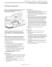
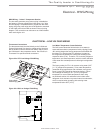
Charging The System
There are two methods of charging a refrigerant system. One
method is the total charge method, where the volume of the
system is determined and the refrigerant is measured and
added into the evacuated system. The other method is the
partial charge method where a small initial charge is added
to an evacuated system, and remaining refrigerant added
during operation.
Total Charge Method - See Table 4 for the compressor
section basic charge. For line sets with 3/8” liquid lines
add 0.6 ounces of refrigerant to the basic charge for every
installed foot of liquid line [0.6 grams per cm]. Add 1.2 oz.
per foot [1.1 grams per cm] if using l/2” line. Once the total
charge is determined, the factory pre-charge (Table 4) is
subtracted and the remainder is the amount needed to be
added to the system. This method should be used with the
ARI matched air handler.
EXAMPLE: R22 model 048 with 40 feet [12 meters] of
installed liquid line (3/8” O.D.). The basic charge of model
048 is 115 oz [3.26 kg]. The 40 ft. [12 meter] 3/8” line set
requires 24 oz. [0.72 kg] (40 ft. x 0.6 oz./ft = 24 oz. -- 1200cm
x 0.6g/cm = 720g). Total charge = 115 + 24 = 139 oz [3.26 +
0.72 = 3.98 kg]. The compressor section is shipped from the
factory with 130 oz. [3.69 kg] of refrigerant (for 25 ft [7.6m]
lineset), so the amount to be added is 9 oz. [0.29 kg] (total
charge - shipped charge = charge to be added).