


31
The Quality Leader in Conditioning Air
Residential Split - 60Hz R22 &R410A
Rev.: 5 June, 2008
www.heatcontoller.com
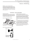
CXM Controls
Safety Features – CXM Control
The safety features below are provided to protect the
compressor, heat exchangers, wiring and other components
from damage caused by operation outside of design
conditions.
Anti-short cycle protection: The control features a 5 minute
anti-short cycle protection for the compressor.
Note: The 5 minute anti-short cycle also occurs at power up.
Random start: The control features a random start upon power
up of 5-80 seconds.
Fault Retry: In Fault Retry mode, the Status LED begins slowly
flashing to signal that the control is trying to recover from a
fault input. The control will stage off the outputs and then “try
again” to satisfy the thermostat input call. Once the thermostat
input call is satisfied, the control will continue on as if no fault
occurred. If 3 consecutive faults occur without satisfying the
thermostat input call, the control will go into “lockout” mode.
The last fault causing the lockout will be stored in memory and
can be viewed by going into test mode. Note: FP1/FP2 faults
are factory set at only one try.
Lockout: In lockout mode, the status LED will begin fast
flashing. The compressor relay is turned off immediately.
Lockout mode can be “soft” reset by turning off the thermostat
(or satisfying the call). A “soft” reset keeps the fault in memory
but resets the control. A “hard” reset (disconnecting power to
the control) resets the control and erases fault memory.
Lockout with emergency heat: While in lockout mode, if W
becomes active (CXM), emergency heat mode will occur.
High pressure switch: When the high pressure switch opens due
to high refrigerant pressures, the compressor relay is de-energized
immediately since the high pressure switch is in series with the
compressor contactor coil. The high pressure fault recognition is
immediate (does not delay for 30 continuous seconds before de-
energizing the compressor).
High pressure lockout code = 2
Example: 2 quick flashes, 10 sec pause, 2 quick flashes, 10
sec. pause, etc.
Low pressure switch: The low pressure switch must be open and
remain open for 30 continuous seconds during “on” cycle to be
recognized as a low pressure fault. If the low pressure switch
is open for 30 seconds prior to compressor power up it will be
considered a low pressure (loss of charge) fault. The low pressure
switch input is bypassed for the initial 60 seconds of a compressor
run cycle.
Low pressure lockout code = 3
Water coil low temperature (FP1): The FP1 thermistor
temperature must be below the selected low temperature limit
setting for 30 continuous seconds during a compressor run cycle
to be recognized as a FP1 fault. The FP1 input is bypassed for
the initial 60 seconds of a compressor run cycle. FP1 is set at the
factory for one try. Therefore, the control will go into lockout mode
once the FP1 fault has occurred.
FP1 lockout code = 4
Air coil low temperature (FP2): The FP2 thermistor temperature
must be below the selected low temperature limit setting for
30 continuous seconds during a compressor run cycle to be
recognized as a FP2 fault. The FP2 input is bypassed for the
initial 60 seconds of a compressor run cycle. FP2 is set at the
factory for one try. Therefore, the control will go into lockout mode
once the FP2 fault has occurred.
FP2 lockout code = 5
Condensate overflow: The condensate overflow sensor
must sense overflow level for 30 continuous seconds to
be recognized as a CO fault. Condensate overflow will be
monitored at all times.
CO lockout code = 6
Over/under voltage shutdown: An over/under voltage condition
exists when the control voltage is outside the range of 19VAC
to 30VAC. Over/under voltage shut down is a self-resetting
safety. If the voltage comes back within range for at least 0.5
seconds, normal operation is restored. This is not considered
a fault or lockout. If the CXM is in over/under voltage shutdown
for 15 minutes, the alarm relay will close.
Over/under voltage shut down code = 7
Unit Performance Sentinel-UPS (patent pending): The UPS
feature indicates when the heat pump is operating inefficiently.
A UPS condition exists when:
a) In heating mode with compressor energized, FP2 is
greater than 125°F [52°C] for 30 continuous seconds, or:
b) In cooling mode with compressor energized, FP1 is
greater than 125°F [52°C] for 30 continuous seconds, or:
c)
In cooling mode with compressor energized, FP2 is less
than 40°F [4.5°C] for 30 continuous seconds. If a UPS
condition occurs, the control will immediately go to UPS
warning. The status LED will remain on as if the control
is in normal mode. Outputs of the control, excluding LED
and alarm relay, will NOT be affected by UPS. The UPS
condition cannot occur during a compressor off cycle.
During UPS warning, the alarm relay will cycle on and
off. The cycle rate will be “on” for 5 seconds, “off” for 25
seconds, “on” for 5 seconds, “off” for 25 seconds, etc.
UPS warning code = 8
Swapped FP1/FP2 thermistors: During test mode, the control
monitors to see if the FP1 and FP2 thermistors are in the
appropriate places. If the control is in test mode, the control will
lockout, with code 9, after 30 seconds if:
a) The compressor is on in the cooling mode and the FP1
sensor is colder than the FP2 sensor, or:
b) The compressor is on in the heating mode and the FP2
sensor is colder than the FP1 sensor.
Swapped FP1/FP2 thermistor code = 9.
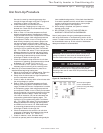
Diagnostic Features
The LED on the CXM board advises the technician of the
current status of the CXM control. The LED can display either
the current CXM mode or the last fault in memory if in test
mode. If there is no fault in memory, the LED will flash Code 1
(when in test mode).