


HEAT CONTROLLER, INC. WATER-SOURCE HEAT PUMPS
Residential Split - 60Hz R22 &R410A
Rev.: 5 June, 2008
30
Heat Controller, Inc. Water-Source Heating and Cooling Systems
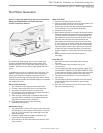
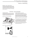
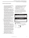
CXM Control
For detailed control information, see CXM Application,
Operation and Maintenance (IOM) manual.
Field Selectable Inputs
Test mode: Test mode allows the service technician to check
the operation of the control in a timely manner. By momentarily
shorting the test terminals, the CXM control enters a 20
minute test mode period in which all time delays are sped up
15 times. Upon entering test mode, the status LED will flash
a code representing the last fault. For diagnostic ease at the
thermostat, the alarm relay will also cycle during test mode.
The alarm relay will cycle on and off similar to the status LED
to indicate a code representing the last fault, at the thermostat.
Test mode can be exited by shorting the test terminals for 3
seconds.
Retry Mode: If the control is attempting a retry of a fault, the
status LED will slow flash (slow flash = one flash every 2
seconds) to indicate the control is in the process of retrying.
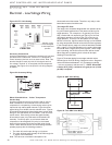
Field Conguration Options
Note: In the following field configuration options, jumper wires
should be clipped ONLY when power is removed from the
CXM control.
Water coil low temperature limit setting: Jumper 3 (JW3-
FP1 Low Temp) provides field selection of temperature limit
setting for FP1 of 30°F or 10°F [-1°F or -12°C] (refrigerant
temperature).
Not Clipped = 30°F [-1°C]. Clipped = 10°F [-12°C].
Air coil low temperature limit setting: Jumper 2 (JW2-FP2
Low Temp) provides field selection of temperature limit
setting for FP2 of 30°F or 10°F [-1°F or -12°C] (refrigerant
temperature). Note: This jumper should only be clipped
under extenuating circumstances, as recommended by
the factory.
Not Clipped = 30°F [-1°C]. Clipped = 10°F [-12°C].
Alarm relay setting: Jumper 1 (JW1-AL2 Dry) provides field
selection of the alarm relay terminal AL2 to be jumpered to
24VAC or to be a dry contact (no connection).
Not Clipped = AL2 connected to R. Clipped = AL2 dry contact
(no connection).
DIP Switches
Note: In the following field configuration options, DIP
switches should only be changed when power is removed
from the CXM control.
DIP switch 1: Unit Performance Sentinel Disable - provides
field selection to disable the UPS feature.
On = Enabled. Off = Disabled.
DIP switch 2: Stage 2 Selection - provides selection of
whether compressor has an “on” delay. If set to stage 2, the
compressor will have a 3 second delay before energizing.
Also, if set for stage 2, the alarm relay will NOT cycle during
test mode.
On = Stage 1. Off = Stage 2
DIP switch 3: Not Used.
DIP switch 4: DDC Output at EH2 - provides selection for
DDC operation. If set to “DDC Output at EH2,” the EH2
terminal will continuously output the last fault code of
the controller. If set to “EH2 normal,” EH2 will operate as
standard electric heat output.
On = EH2 Normal. Off = DDC Output at EH2.
NOTE: Some CXM controls only have a 2 position DIP switch
package. If this is the case, this option can be selected by
clipping the jumper which is in position 4
of SW1.
Jumper not clipped = EH2 Normal. Jumper clipped = DDC
Output at EH2.
DIP switch 5: Factory Setting - Normal position is “On.” Do
not change selection unless instructed to do so by
the factory.
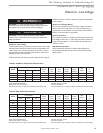
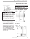
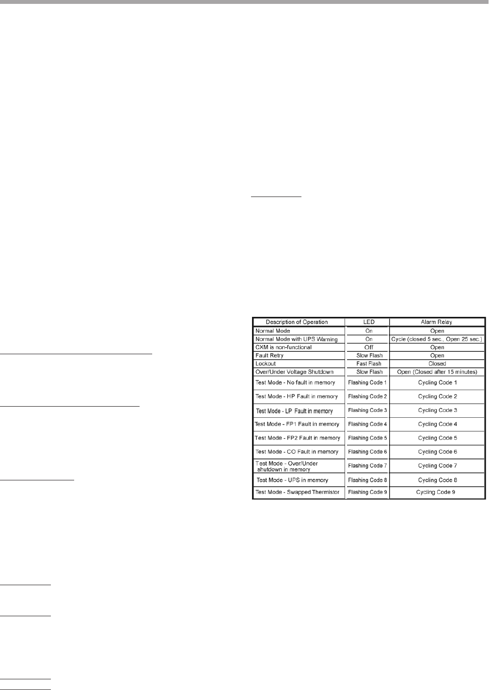
-Slow Flash = 1 flash every 2 seconds
-Fast Flash = 2 flashes every 1 second
-Flash code 2 = 2 quick flashes, 10 second pause, 2 quick
flashes, 10 second pause, etc.
-On pulse 1/3 second; off pulse 1/3 second
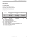
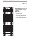
CXM Controls
Table 9a: CXM LED And Alarm
Relay Operations