


33
The Quality Leader in Conditioning Air
Residential Split - 60Hz R22 &R410A
Rev.: 5 June, 2008
www.heatcontoller.com
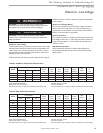
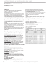
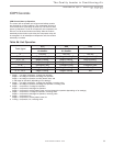
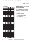
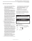
Table 9b: Unit Operation
CXM Controls
CXM Control Start-up Operation
The control will not operate until all inputs and safety controls
are checked for normal conditions. The compressor will have a
5 minute anti-short cycle delay at power-up. The rst time after
power-up that there is a call for compressor, the compressor will
follow a 5 to 80 second random start delay. After the random
start delay and anti-short cycle delay, the compressor relay will
be energized. On all subsequent compressor calls, the random
start delay is omitted.
T-stat signal
HTS HSS HSS
Variable Speed
Air Handler
Variable Speed
Air Handler
PSC Air Handler
G Fan only Fan only Fan only
G, Y or Y1 Stage 1 heating
1
Stage 1 heating
3
Stage 1 heating
5
G, Y1, Y2 Stage 2 heating
1
Stage 2 heating
3
Stage 2 heating
5
G, Y1, Y2, W Stage 3 heating
1
Stage 3 heating
3
N/A
G, W Emergency heat Emergency heat Emergency heat
G, Y or Y1, O Stage 1 cooling
2
Stage 1 cooling
4
Cooling
6
G, Y1, Y2, O Stage 2 cooling
2
Stage 2 cooling
4
N/A
1 Stage 1 = 1st stage compressor, 1st stage fan operation
Stage 2 = 2nd stage compressor, 2nd stage fan operation
Stage 3 = 2nd stage compressor, auxiliary electric heat, 2nd
or 3rd stage fan operation (depending on fan settings)
2 Stage 1 = 1st stage compressor, 1st stage fan operation, reversing valve
Stage 2 = 2nd stage compressor, 2nd stage fan operation, reversing valve
3 Stage 1 = compressor, 1st stage fan operation
Stage 2 = compressor, 2nd stage fan operation
Stage 3 = compressor, auxiliary electric heat, 2nd or 3rd stage fan operation (depending on fan settings)
4 Stage 1 = compressor, 1st stage fan operation, reversing valve
Stage 2 = compressor, 2nd stage fan operation, reversing valve
5 Stage 1 = compressor, fan
Stage 2 = compressor, auxiliary electric heat, fan
6 Cooling = compressor, fan, reversing valve