


8
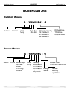
Installation Manual VMH SerieS Heat Controller, Inc.
3
Read completely, then follow step by step.
Indoor unit
Do not expose the indoor unit to heat or steam.
Select a place where there are no obstacles
in front or around the unit.
Make sure that condensation drainage can
be conveniently routed away.
Do not install near a doorway.
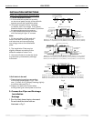
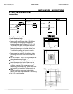
Ensure that the proper clearance is maintained per Fig.1.
Use a stud finder to locate studs to prevent unnecessary damage to the wall.
Variations in pipe length may require adjustment to refrigerant charge.
There should not be any direct sunlight. Otherwise, the sun will fade the plastic cabinet and
affect its appearance. If unavoidable, sunlight preventi
on should be taken into consideration.
Outdoor unit
If an awning is built over the outdoor unit to
prevent direct sunlight or rain exposure,
make sure that heat radiation from the
condenser is not restricted.
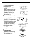
Ensure that the clearance is maintained
per Fig 2.
Do not place animals and plants in the path
of the air inlet or outlet.
Take the air conditioner weight into account
and select a place where noise and vibration
will not be an issue.
Select a place so that the warm air and noise from
the air conditioner do not disturb neighbors.
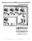
INSTALLATION INSTRUCTIONS
More than 1 ft.(30cm)
More than 2 ft.(60cm)
More than 1 ft.(30cm)
More than 6.5 ft.(200cm)
Fig.2
More than 6.5 ft.(2.0m)
More than 6 in.(15cm)
More than 5 in.(12cm)
More than 5 in.(12cm)
Fig.1
1. Selecting Installation Place
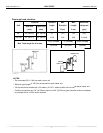
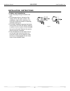
2. Four-way cassette type
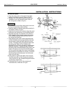
1. Install the main body
A. The existing ceiling (to be horizontal)
a. Please cut a quadrangular hole of 600¡600mm
in the ceiling according to the shape of the
installation paper board. (Refer to Fig.15 & 16)
The center of the hole should be at the same
position of that of the air conditioner body.
Determine the lengths and outlets of the conn-
ecting pipe, drain pipe and cables.
To balance the ceiling and to avoid vibration,
please enforce the ceiling when necessary.
b. Please select the position of installation hooks
according to the hook holes on the installation
board.
Drill four holes of 12mm, 50~55mm deep at the
selected positions on the ceiling. Then embed
the expansible hooks(fittings).
Face the concave side of the installation hooks
toward the expansible hooks. Determine the
length of the installation hooks from the height
of ceiling, then cut off the unnecessary part.
If the ceiling is extremely high, please determine
the length of the installation hook according to
facts.
Cut the installation hook open in the middle
position, then use apropriate length of reinforcing
rod ( 12) to weld together.
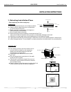
Ceiling Cassette installation
9
INSTALLATION INSTRUCTIONS
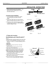
Installation Fittings
Tubing & Fittings
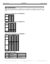
1. Expansible hook.................................4
2. Installation hook.................................4
3. Installation paper board.....................1
4. Bolt M6¡12.....................4M5¡16 or
Included Pans
6. Connecting pipe group.........................1
8. Soundproof / insulation sheath.............2
7. Binding tape.........................................6
Remote controller
9. Remote controller...........................1
10. Holder.............................................1
11. Mounting screw(ST2.9×10-C-H) ...2
12. Alkaline dry batteries (AM4)............2
5. Fernte Core Filter..................................1
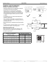
A 11” (280mm)
Clearance
Fig.13
Fig.14
Ground
Outlet
Outlet
7.5ft (>2300)
Inlet
3.5ft (>1000)
3.5ft (>1000)
3.5ft (>1000)
3.5 ft (>1000)
Fig.15
Drain side
A
16.61” (422)
1” (28.5)
2.64” (67)
15.79” (401)(Hook location)
24.06” (611)(Hook location)
22.83” (580)(Body)
22.83” (580)(Body)
23.62” (600)(Ceiling hole)
23.62” (600)(Ceiling hole)
25.6” (650)(Panel)
25.6” (650)(Panel)