


10
Installation Manual VMH SerieS Heat Controller, Inc.
6
INSTALLATION INSTRUCTIONS
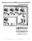
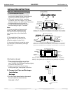
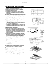
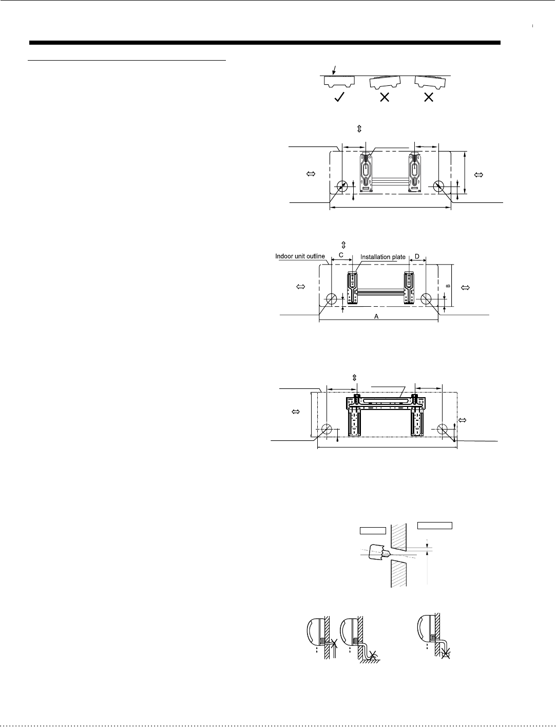
Fig.4
Correct orientation
of Installation Plate
Wall
Indoor
Outdoor
3/16”-1/4”(5-7mm)
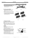
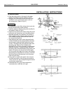
Fig.6
Fig.5
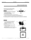
Indoor unit installation(wall-mounted type)
2. Drill a hole in the wall
Note:
1. Fit the Installation Plate
1. Fit the installation plate horizontally
on structural parts (studs) of the wall with
spaces around the installation plate.
2. If the wall is made of brick, concrete
or the like, drill five or eight 3/16”(5mm)
diameter holes in the wall.Insert Clip anchor
for appropriate mounting screws.
3. Fit the installation plate on the wall
with five to eight type “A” screws.
1. Fit the Installation Plate and drill
holes in the wall according to the
wall structure and corresponding
mounting points on the in
stallation
plate.
2. The Installation Plate may be
slightly different according to the
different models of indoor unit.
3. Use a stud finder to locate the studs
to prevent any unnecessary damage
to the wall.
1. Determine hole positions according
to the diagram detailed in Fig.5. Drill
one (1) hole 2-9/16”(¦65mm) slanting slightly
to outdoor side see Fig. 6.
2. Always use wall hole conduit when
drilling metal grid, metal plate or the like.
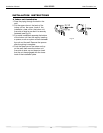
3. Connective Pipe and Drainage
Installation
1. Run the drain hose sloping downward.
Do not install the drain hose as
illustrated in Fig.7.
Drainage
Fig.7
Do not block water flow by a rise.
Do not put the end of
drain hose into water.
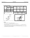
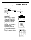
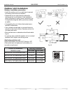
Indoor unit outline
Installation plate
292
Right rear side
refrigerant
pipe hole ¦2-9/16”(65)
Left rear side
refrigerant
pipe hole ¦2-9/16”(65)
4.75”(120mm) or
more to wall
4.75”(120mm) or
more to wall
A
45
D
C
45
A
1.75”(45)
B
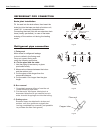
Right rear side
refrigerant
pipe hole ¦2-9/16”(65)
Installation plate
Indoor unit outline
Left rear side
refrigerant
pipe hole ¦2-9/16”(65)
6”(150mm) or more to ceiling
4.75”(120mm) or
more to wall
4.75”(120mm) or
more to wall
Model A) A: 27.95”(7-10mm), B:9.84”(250mm), C:3.94”(100mm), D: 4.33”(110mm)
Model B) A: 31.10”(790mm), B:10.43”(265mm), C:3.94”(100mm), D: 5.91”(150mm)
1.75”(45)
C
D
6”(150mm) or more to ceiling
4.75”(120mm) or
more to wall
Right rear side
refrigerant
pipe hole ¦2-9/16”(65)
1.75”(45)
1.75”(45)
Left rear side
refrigerant
pipe hole ¦2-9/16”(65)
4.75”(120mm) or
more to wall
6”(150mm) or more to ceiling
Model A) A: 27.95”(7-10mm), B:9.84”(250mm), C:3.94”(100mm), D: 4.33”(110mm)
Model B) A: 31.10”(790mm), B:10.83”(265mm), C:3.94”(100mm), D: 3.35”(85mm)
Model C) A: 33.46”(850mm), B:11.42”(290mm), C:3.94”(100mm), D: 4.53”(115mm)
Model A) A: 36.22”(920mm), B:11.54”(293mm), C:5.91”(150mm), D: 7.28”(185mm)
Model B) A: 39.17”(995mm), B:11.54”(293mm), C:5.91”(150mm), D: 7.87”(200mm)
Model C) A: 33.46”(850mm), B:12.01”(305mm), C:5.91”(150mm), D: 5.71”(145mm)