


7
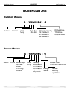
Heat Controller, Inc. VMH SerieS Installation Manual
10
7. Installation Details
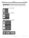
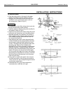
7.1 Wrench torque sheet for installation
Outside diameter Torque Additional tightening torque
mm inch
N
.
m
N
.
m
Ф6.35 1/4 15(153kgf.cm) 16(163kgf.cm)
Ф9.52 3/8 25(255kgf.cm) 26(265kgf.cm)
Ф12.7 1/2 35(357kgf.cm) 36(367kgf.cm)
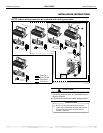
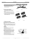
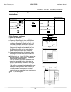
7.2 Connecting the cables
The power wiring should always follow NEC and local codes, with respect to the unit’s, rating plate. See
installation manual for additional information. Main power connection is 208/230V/1PH~60HZ.
The communicating cable, which connects between the indoor and outdoor units must meet all NEC and
local codes, with respect to the unit’s rating plate. We recommend using 14 AWG/4 conductor Stranded THHN
6
Ф Ф V cable.
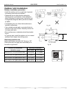
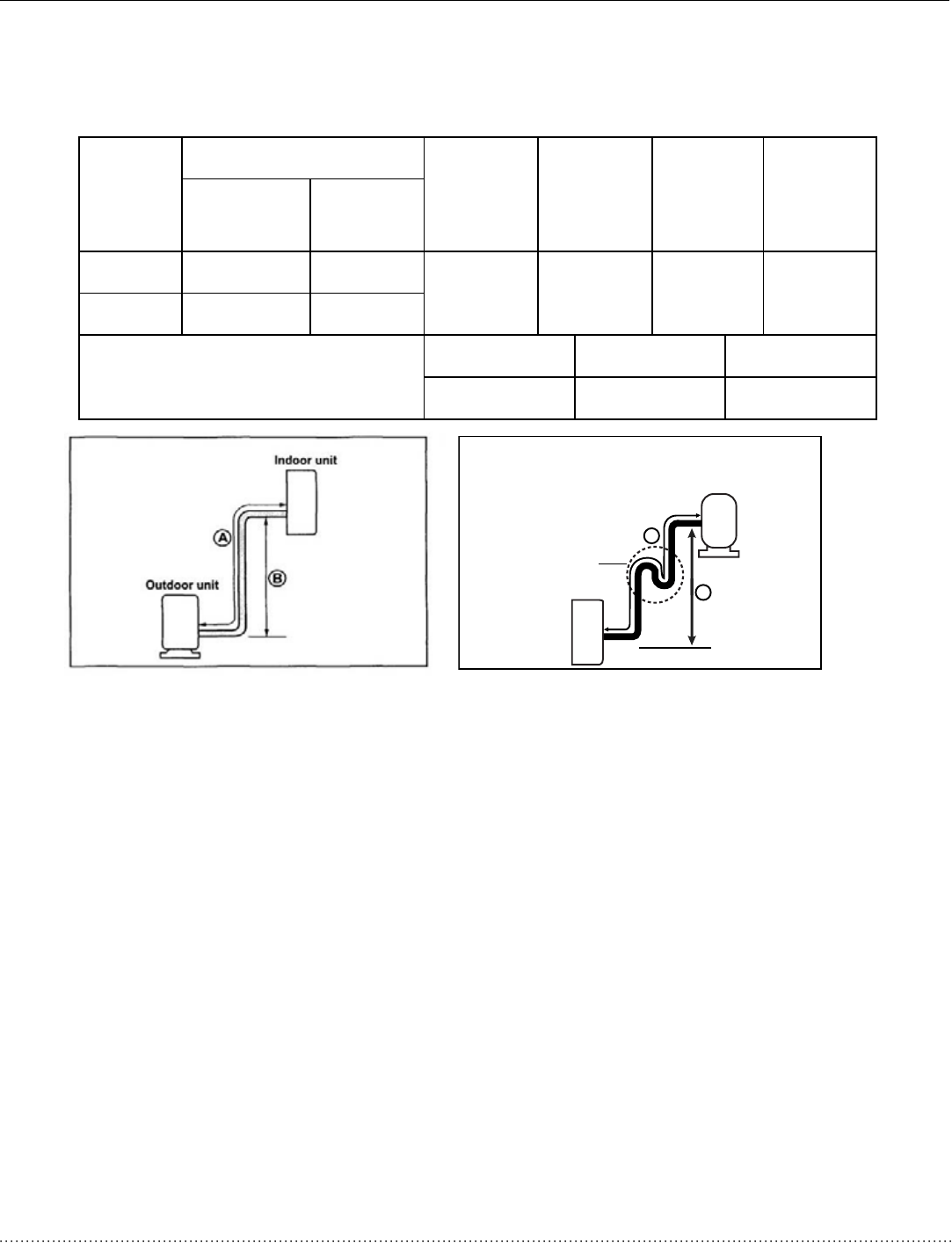
Pipe length and elevation
Unit
Pipe size
Standard
length
(m)
Max.
Elevation
B (m)
Max.
Length
A (m)
Additional
refrigerant
(g/m)
Gas inch
(mm)
Liquid inch
(mm)
9K 3/8’’ (Ф9.52) 1/4’’ (Ф6.35)
(5)
16.5ft
(10)
33ft
(15)
50ft
(20)
0.2 oz/ft
12K/18K 1/2’’ (Ф12.7) 1/4’’ (Ф6.35)
Max. Total length for all rooms
Dual-zone(m) Tri-zone(m) Quad-zone(m)
(30)100ft (45)150ft (60)200ft
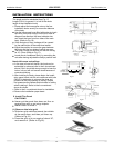
NOTES:
Capacity test is based on standard length and maximum allowance length is based on reliability.
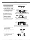
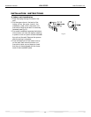
Oil trap should be installed per (3-5 meters)10-15ft.
Outdoor connections are ¼” (Ф6.35 mm) liquid and 3/8” (Ф9.52 mm) gas, therefore a reducer is
provided with all 12/18k indoor sections.
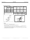
NOTES:
• Do not exceed 50 ft. (15m) per each indoor unit.
• Minimum pipe lenght of 10ft (3m) is required for each indoor unit.
• Oil trap should be installed per (3-5 meters) 10-15 ft., where outdoor unit is located above indoor unit.
• Outdoor connections are 1/4” (f6.35 mm) liquid and 3/8” (f9.52 mm) gas, therefore a are nut adapter
is provided with all 12/18k indoor sections.
2LOWUDS
,QGRRUXQLW
2XWGRRUXQLW
$
%