


11
Heat Controller, Inc. VMH SerieS Installation Manual
7
INSTALLATION INSTRUCTIONS
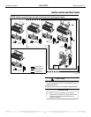
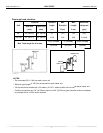
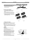
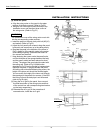
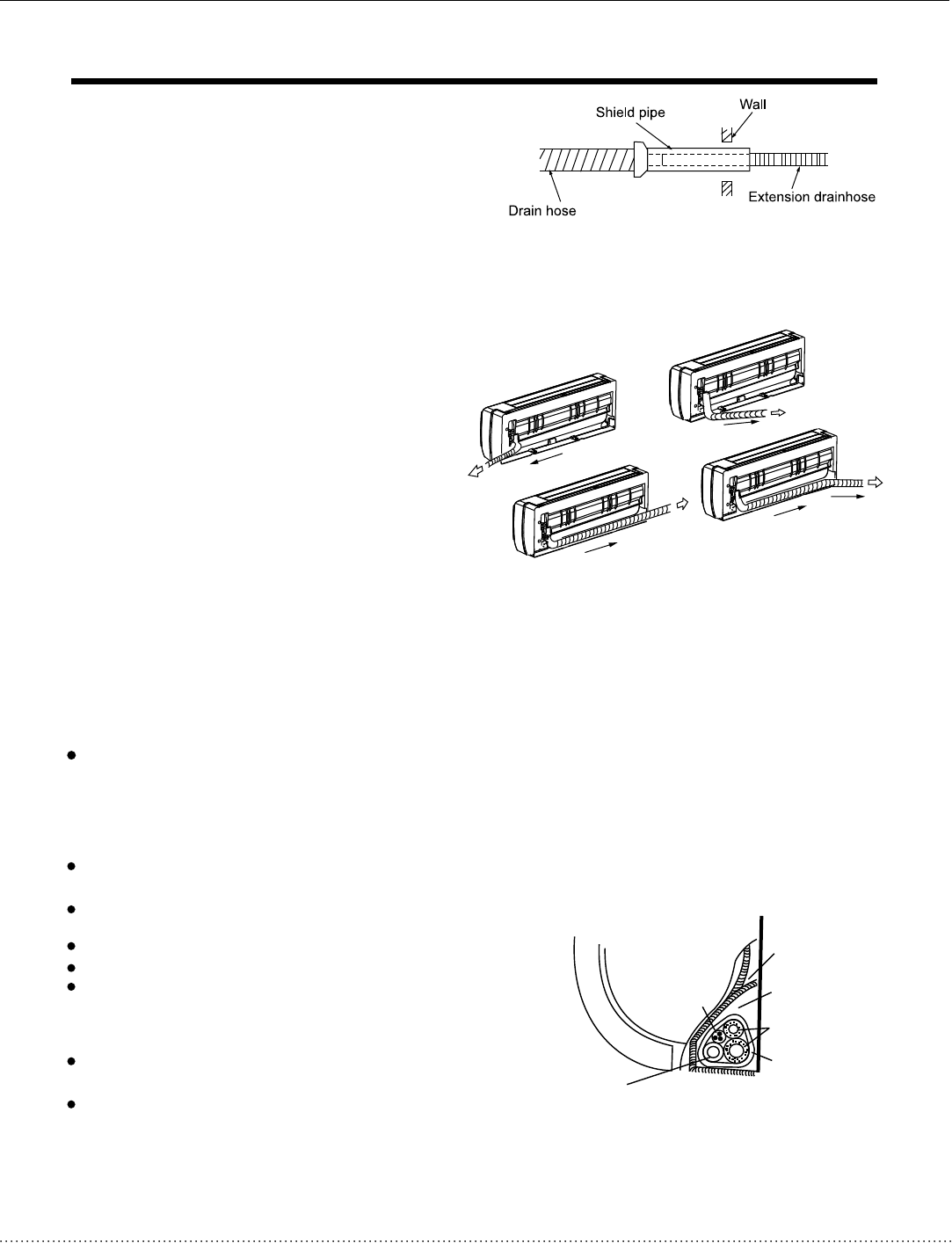
1. For the left-hand and right-hand piping,
remove the pipe cover from the side
panel.
2. For the rear-right-hand and rear-left-hand
piping, install the piping as shown in Fig.10.
3. Fix the end of the connective pipe. (Refer
to Tightening Connection in REFRIGERANT
PIPING CONNECTION)
Connective pipe installation
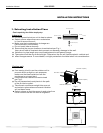
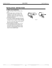
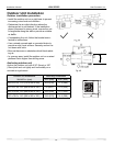
2. When connecting the drain extension hose,
insulate the connection of extension
drain hose with a shield pipe, do not let
the drain hose slack.
Right-hand piping
Left-hand piping
Rear-right piping
Rear-left piping
Fig.8
Fig.9
Fig.10
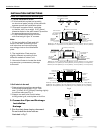
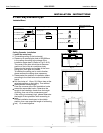
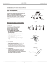
4. Piping and wrapping
Bundle the tubing, connecting cable, and drain
hose with tape securely, evenly as shown in
Fig.11.
Because the condensed water from rear of the
indoor unit is gathered in ponding box and is
piped out of room. Do not put anything else in
the box.
Indoor unit
Connective
pipe
Pipe room
Ponding box
Wrapping belt
Connective
cable
Drain hose
.
.
.
.
.
.
.
.
.
.
.
.
.
.
.
.
.
.
.
.
.
.
.
.
.
.
.
.
.
. .
.
Fig.11
Connect the indoor unit first, then the
outdoor unit.
Do not allow the piping to let out from
the back of the indoor unit.
Be careful not to let the drain hose slack.
Heat insulate both of the auxiliary piping.
Be sure that the drain hose is located at
the lowest side of the bundle. Locating
at the upper side can cause drain pan
to overflow inside the unit.
Never intercross nor intertwine the power
wire with any other wiring.
Run the drain hose sloped downward to
drain out the condensed water smoothly.
CAUTION