


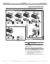
14
Installation Manual VMH SerieS Heat Controller, Inc.
10
INSTALLATION INSTRUCTIONS
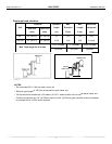
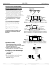
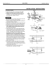
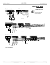
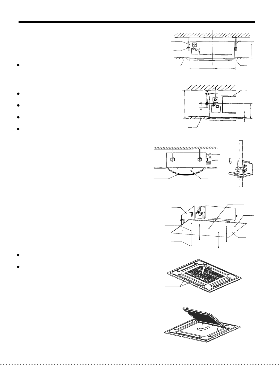
The length could be calculated from Fig.17:
Length=210+L(in general, L is half of the whole
length of the installation hook)
c. Please adjust the hexangular nuts on the four
installation hooks evenly, to ensure the balance
of the body.
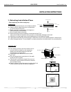
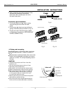
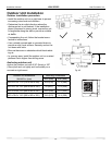
Use the transparent hose filled with water to check
the lever of the main body from the four sides or
diagonal line direction, the lever indicator also
can check the lever from four sides of the main
body .(Refer to Fig.18)
If the drainpipe is awry, leakage will be caused
by the malfunction of the water-level switch.
Adjust the position to ensure the gaps between
the body and the four sides of ceiling are even.
The body's lower part should sink into the ceiling
for 10~12mm (Refer to Fig.17).
Locate the air conditioner firmly by wrenching the
nuts after having adjusted the body's position well.
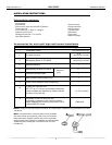
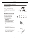
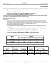
2. Install The Panel
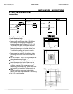
(1) Remove the inlet grid.
CAUTIONS
Never put the panel face down on floor or
against the wall, or on bulgy objects.
Never crash or strike it.
a. Slide two grid switches toward the middle
at the same time, and then pull them up.
(Refer to Fig.21)
o
b. Draw the grid up to an angle of about 30 ,
and remove it. (Refer to Fig.22)
New built houses and ceilings
a. In the case of new built house, the hook can be
embedded in advance (refer to the A.b mentioned
above). But it should be strong enough to bear the
indoor unit and will not become loose because of
concrete shrinking.
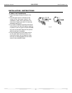
b. After installing the body, please fasten the install-
ation paper board onto the air conditioner with bolts
(M5¡16) to determine in advance the sizes and
positions of the hole opening on ceiling. Please
, first guarantee the flatness and horizontal of ceiling
when installing it. Refer to the A.a mentioned
above for others.
c. Refer to the A.c mentioned above for installation.
d. Remove the installation paper board.
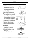
Fig. 16
Ceiling
Panel
Hook
A
285
Nut
Body
600
L
10-12
176
34
Fig. 17
Ceiling
Body
H(ceiling height)
Fig.18
Fig.19
Colourless
trans parent pipe
Horizontal
indicator
Fig.20
Body
Fixing hole
Installation
paper board
Screw M5¡16
(Accessory)
Installation
paper board
Hook hole
Central hole
Grid switch
Fig.21
o
45
Fig.22