


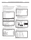

3
Heat Controller, Inc. 7602-443 COMMUNICATING, PROGRAMMABLE THERMOSTAT Installation Manual
The 7602-443 Communicating, Programmable Thermostat is
the perfect compliment to a Geothermal Heat Pump System
and represents a signifi cant advancement in thermostat
communicating technology. For homeowners, the 7602-
443 provides highly customizable climate control features
designed to maximize comfort and reduce the amount of
energy consumed by the Geothermal Heat Pump System.
For dealers, it represents a signifi cant advancement in con-
fi guration, monitoring and diagnostics from the thermostat.
Please read the following instructions carefully to maximize
the comfort and cost-saving potential of your Geothermal
Heat Pump System.
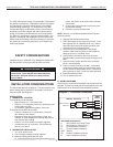
SAFETY CONSIDERATIONS
Improper wiring or installation may damage thermostat. Wir-
ing must conform to local and national electrical codes
WARNING!
WARNING!
Before installing thermostat, turn off all
power to unit. There may be more than one power
disconnect. Electrical shock can cause personal
injury or death.
INSTALLATION CONSIDERATIONS
The thermostat requires no batteries. The thermostat is not a
power stealing device and MUST have both R and C termi-
nals connected. See Diagram 1.
INSTALLATION
I. THERMOSTAT LOCATION
Thermostat should be mounted:
• Approximately 5 ft. (1.5m) above fl oor.
• Close to or in a frequently used room, preferably on an
inside partitioning wall.
• On a section of wall without pipes or duct work.
Thermostat should NOT be mounted:
• Close to a window, on an outside wall, or next to a
door leading to the outside.
• Exposed to direct light and heat from a lamp, sun,
fi replace, or other temperature-radiating object which
may cause a false reading.
• Close to or in direct airfl ow from supply registers.
• In areas with poor air circulation, such as behind a
door or in an alcove.
II. THERMOSTAT INSTALLATION
1. Turn off all power to unit.
2. If an existing thermostat is being replaced:
A. Remove existing thermostat from wall.
B. Disconnect wires from existing thermostat, one at
a time. Be careful not to allow wires to fall back
into the wall.
C. As each wire is disconnected, record wire color
and terminal marking.
D. Discard or recycle old thermostat.
NOTE: Mercury is a hazardous waste and MUST be dis-
posed of properly.
3. Separate the thermostat from base.
4. Route thermostat wires through hole in base. Level
base against wall (for aesthetic value only - thermo-
stat need not be leveled for proper operation) and
mark wall through 2 mounting holes.
5. Drill two 3/16-in. mounting holes in wall where
marked. (Note: Mounting holes on thermostat are
designed to fi t on a horizontal J-box).
6. Secure base to wall with 2 anchors and screws
provided making sure all wires extend through hole in
base.
7. Connect wires to proper terminal of the connector
block in the thermostat.
8. Push any excess wire back into wall. Excess wire
inside the thermostat case can interfere with proper
air fl ow across the temperature sensor. Seal hole in
wall to prevent air leaks. Leaks can affect operation.
9. Install thermostat on base.
10. Turn on power to the unit.
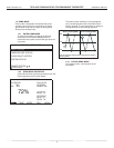
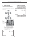
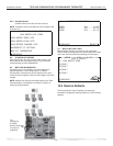
III. WIRING DIAGRAMS
All excess wire should be pushed back into the wall as far as
possible. Excess wire inside the thermostat plastic case may
interfere with the air fl ow across the temperature sensor.
Thermostat Connections
C 24V Common for Control Circuit
R 24V Supply for Control Circuit
A+ Communications (Positive)
B – Communications (Negative)
GND Ground
OD Outdoor Temperature Sensor
ID Indoor Temperature Sensor
ATC32U** Thermostat
24Vac Hot
DXM2
Control
24V
Comm +
A+
A+
Comm -
B-
B-
OD
ID
GND
Outdoor
Sensor
(Optional)
Remote Indoor
Sensor
(Optional)
24Vac Common
Gnd
R
C
Diagram 1: Thermostat Connections
7602-443