


12
Installation Manual 7602-443 COMMUNICATING, PROGRAMMABLE THERMOSTAT Heat Controller, Inc.
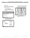
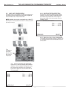
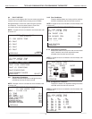
9.2 CONTROL DIAGNOSTICS
Control Diagnostics mode allows the service personnel to
view the status of all physical inputs, switches, temperature
sensor readings, as well as the operational status of the
pump at the thermostat.
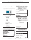
Navigate between diagnostic screens using the left/right
arrow buttons.
NOTE 1: If multiple units are connected to one thermostat,
refer to section 9.6.
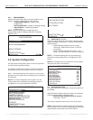
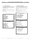
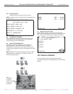
9.3 DIPSWITCH CONFIGURATION
Dipswitch Confi guration mode allows the service personnel
to view the status of all dipswitch settings for the connected
communicating control (DXM2/AXM) at the thermostat.
Navigate between confi guration screens using the left/right
arrow buttons.
NOTE 1: The unit control dipswitch settings cannot be
changed from the thermostat.
NOTE 2: If multiple units are connected to one thermostat,
refer to section 9.6.
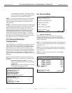
CONTROL STATUS
TEMPERATURES
LT1 TEMP 38.1
LT2 TEMP 79.9
COMP DISCHARGE 157.7
HOT WATER EWT 121.5
LEAVING AIR 75.1
LEAVING WATER 73.3
ENTERING WATER 78.5
CONTROL VOLTAGE 26.4
ECM BLOWER RPM 550
ECM TARGET CFM 800
ECM BLWR STATIC N/A
PREVIOUS NEXT
CONTROL DIAGNOSTICS
HP SWITCH CL
LOC SWITCH CL
Y1 PHYSICAL INPUT ON
Y2 PHYSICAL INPUT OFF
W PHYSICAL INPUT OFF
O PHYSICAL INPUT ON
G PHYSICAL INPUT ON
H PHYSICAL INPUT OFF
EMERG SHUTDOWN OFF
NIGHT SETBACK OFF
OVR INPUT OFF
PREVIOUS NEXT
CONTROL CONFIGURATION
DIPSWITCH S1
1 ON UPS ENABLED
2 ON DUAL COMP STG 1
3 ON HEAT PUMP TSTAT
4 ON RV O THERMOSTAT
5 ON DEHUMID OFF
6 ON EH2 AUX HEAT
7 ON BOILERLESS
8 ON SEE DXM2 AOM
PREVIOUS NEXT
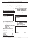
CONTROL CONFIGURATION
DIPSWITCH S2
1 ON \ ACCESSORY 1
2 ON ACCESSORY 2
3 ON/
4 ON \ ACCESSORY 2
5 ON ACTIVE W/ COMP
6 ON /
7 ON H DEHUM INPUT
8 ON FACTORY SETTING
PREVIOUS NEXT
CONTROL CONFIGURATION
DIPSWITCH S3
1 ON FACTORY SETTING
2 OFF HWG TEST OFF
3 OFF HWG SP 125
4 OFF HWG DISABLED
JW3 LT1 SETTING WELL
PREVIOUS