


11
Heat Controller, Inc. 7602-443 COMMUNICATING, PROGRAMMABLE THERMOSTAT Installation Manual
cooling stages for operation. This logic will keep
all active heating or cooling stages energized until
the demand is fully satisfi ed (see NOTE 2).
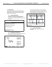
NOTE 1: The Proportional Integral options require fi rst stage
heating or cooling to be active for a minimum of 5 minutes,
before energizing second stage when confi gured for multi
stage operation.
NOTE 2: The Differential option will activate fi rst stage heating
or cooling when the temperature is more than the fi rst stage
differential value (User Manual section 5.6.2.3), below or
above the setpoint. Second stage heating or cooling will be
activated when the temperature is more than the fi rst and
second stage differential values combined (User Manual
section 5.6.2.3), below or above the setpoint. Third stage
heating will be activated when the temperature is more than
the fi rst, second, and third stage differential values combined
(User Manual section 5.6.2.3), below the setpoint.
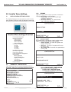
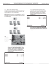
8.0 Demand Reduction
Confi guration
Demand Reduction is activated by an input signal at the unit
control board to reduce the electric load while peak utility
rates are high. The Demand Reduction Confi guration mode
selects which of the available unit control inputs is to be
used as the activation signal. While a physical input signal is
present at the selected input, the thermostat will implement
load reduction by limiting operation or capacity. Refer to
section 5.6.9 in the User Manual for more details on Demand
Reduction.
Adjust the Demand Reduction Confi guration setting using
the up/down arrow buttons. Press the center button to save
changes.
• No Demand Reduction (default) – Demand
Reduction operating mode will not be activated by
a DXM2 input.
• DXM2 Inputs – Assigns a DXM2 input to activate
Demand Reduction operating mode.
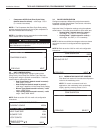
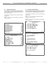
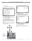
9.0 Service Mode
9.1 MANUAL OPERATION
Manual Operation mode allows the service personnel to
manually command operation for any of the thermostat
outputs, blower speed or valve position to help troubleshoot
specifi c components.
NOTE 1: The ECM Airfl ow adjustment will not be present if the
connected communicating control (DXM2) is not confi gured for
ECM (section 3.3).
NOTE 2: The Valve Position adjustment will not be present if
the connected communicating control (DXM2) is confi gured for
Valve (section 3.1).
NOTE 3: If multiple units are connected to one thermostat,
refer to section 9.6
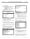
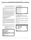
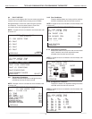
INSTALLER SETTINGS
THERMOSTAT CONFIG
SYSTEM CONFIG
ACCESSORY CONFIG
INPUT DEALER INFO
HUMIDITY CONFIG
TEMPERATURE ALGORITHM
DEMAND REDUCTION CNFG
SERVICE MODE
RESTORY DEFAULTS
ATC32U01
SELECT OPTION
PREVIOUS
SERVICE MODE
MANUAL OPERATION
CONTROL DIAGNOSTICS
DIPSWITCH CONFIG
FAULT HISTORY
CLEAR FAULT HISTORY
SELECT OPTION
PREVIOUS SELECT
MANUAL OPERATING MODE
Y1 COMM OUTPUT OFF
Y2 COMM OUTPUT OFF
W COMM OUTPUT OFF
O COMM OUTPUT OFF
G COMM OUTPUT OFF
H COMM OUTPUT OFF
DH COMM OUTPUT OFF
ECM AIRFLOW 0
PUMP SPEED 0%
TEST MODE OFF
SELECT OPTION
PREVIOUS SELECT
TEST MODE OFF