


Heat & Glo • ST-550TM-IPI • 2142-900 Rev. B • 11/0826
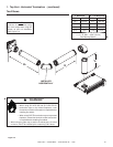
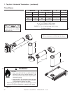
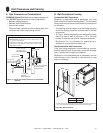
F. Vent Diagrams
General Rules:
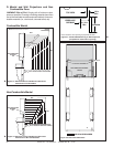
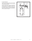
• A maximum of three 90° elbows (or six 45° elbows) may
be used in any vent confi guration. Some elbows may be
installed horizontally. See Figure 7.6.
• Elbows may be placed back to back anywhere in the
system as long as the fi rst 90° elbow is a starter elbow.
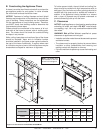
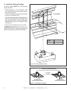
• When penetrating a combustible wall, a wall shield
fi restop must be installed.
• When penetrating a combustible ceiling, a ceiling fi restop
must be installed.
• Horizontal runs of vent do not require vertical rise;
horizontal runs may be level.
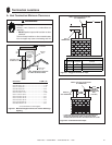
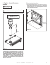
Figure 7.4
One Elbow
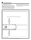
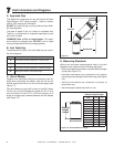
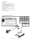
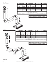
1. Top Vent - Horizontal Termination
V
1
Minimum** H
1
Maximum
1 ft.** 305 mm 2 ft. 610 mm
2 ft.** 610 mm 3 ft. 914 mm
3 ft.** 915 mm 5 ft. 1.5 m
4 ft. 1.2 m 7 ft. 2.1 m
5 ft. 1.5 m 14 ft. 4.3 m
H Max. =14 ft. (4.3 m)
V + H Max. = 40 ft. (12.2 m)
** See Warning below.
H
1
V
1
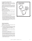
WARNING**
Note: There MUST be a 25%
reduction in total H when using
fl ex vent except when using the
simple up and out installation
(see Figure 7.3).
Fire Risk.
• When using SLP-HRC-SS and SLP-HRC-ZC-SS
termination caps on top vented fi replaces, a two
foot minimum vertical vent section is required before
installing fi rst elbow
.
• When using DVP-TB1 termination cap on top vented
fi replaces, a three foot minimum vertical vent section
is required before installing fi rst elbow.
• When using any other cap, a section of vertical pipe (12 inches
minimum) MUST be installed prior to attaching a 90° elbow.