


Heat & Glo • SL-750TRS-IPI-E, SL-550TRS-IPI-E, SL-350TRS-D, SL-350TRS-IPI • 2120-900 Rev. D • 6/07 43
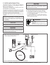
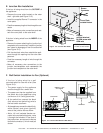
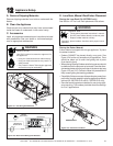
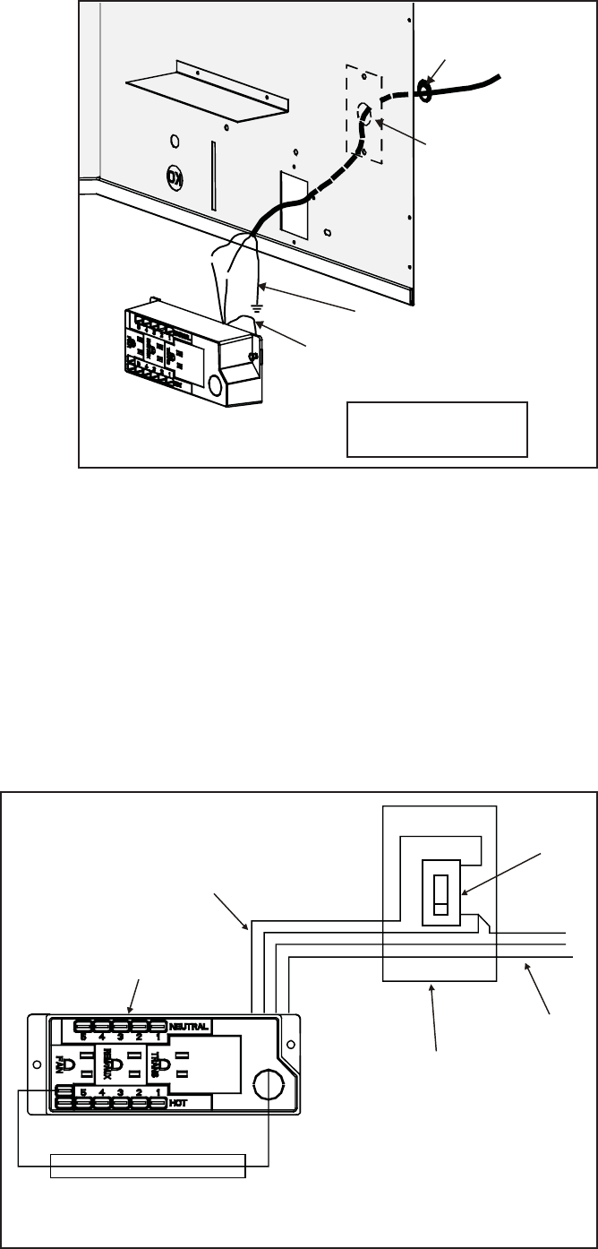
E. Junction Box Installation
WHT
WHT
BLK
BLK
GRN wire
inside box
Copper
ground attached
to GRN screw with
GRN wire
14/2WG
Cover Plate
outside firebox
Romex
Connector
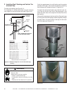
Figure 10.5 Junction Box Detail
If the box is being wired from the OUTSIDE of
the appliance:
• Remove the cover plate located on the outer
shell - right side (see Figure 10.5).
• Install the supplied Romex™ connector in the
cover plate.
• Feed the necessary length of wire through the con-
nector.
• Make all necessary wire connections and reat-
tach the cover plate to the outer shell.
If the box is being wired from the INSIDE of the
appliance:
• Remove the screw attaching the junction box/
receptacle to the outer shell, rotate the junction
box inward to disengage it from the outer shell
(see Figure 10.5).
• Pull the electrical wires from outside the appli-
ance through this opening into the valve com-
partment.
• Feed the necessary length of wire through the
connector.
• Make all necessary wire connections to the
junction box/receptacle and reassemble the
junction box/receptacle to the outer shell.
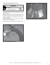
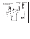
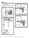
NOTE: Do NOT wire
110VAC to wall switch.
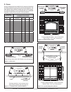
F. Wall Switch Installation for Fan (Optional)
If the box is being wired to a wall
mounted switch for use with a fan (See
Figure 10.6):
• The power supply for the appliance
must be brought into a switch box.
• The power can then be supplied from
the switch box to the appliance using
a minimum of 14-3 with ground wire.
• At the switch box connect the black
(hot) wire and red (switch leg) wire to
the wall switch as shown.
• At the appliance connect the black (hot),
white (neutral) and green (ground)
wires to the junction box as shown.
• Add a 1/4 inch insulated female con-
nector to the red (switch leg) wire, route
it through the knockout in the face of
the junction box, and connect to the top
fan switch connector (1/4 inch male) as
shown.
Red
Red
BlackBlack
Green
Green
White
White
Red
Black
Green
White
SWITCH BOX
JUNCTION BOX
POWER
SUPPLY WIRES
SWITCH
MINIMUM 14-3 AWG
WITH GROUND
Figure 10.6 Junction Box Wired to Wall Switch