


Heat & Glo • SL-750TRS-IPI-E, SL-550TRS-IPI-E, SL-350TRS-D, SL-350TRS-IPI • 2120-900 Rev. D • 6/07 15
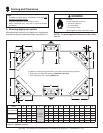
Figure 5.4
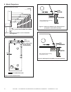
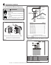
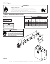
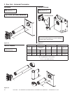
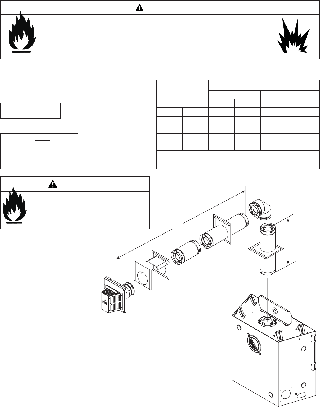
E. Vent Diagrams
1. Top Vent - Horizontal Termination Venting
V Minimum
H
1
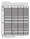
Maximum
SL-350TRS-D SL-550, SL-750TRS-E
90º Elbow 1-1/2 ft. 457 mm 1 ft. 305 mm
1/2 ft. 152 mm 2 ft. 610 mm 2 ft. 610 mm
1-1/2 ft. 457 mm 3 ft. 914 mm 3 ft. 914 mm
2-1/2 ft. 762 mm 5 ft. 1-1/2 m 5 ft. 1-1/2 m
3-1/2 ft. 1.1 m 7 ft. 2.1 m 7 ft. 2.1 m
4-1/2 ft. 1.4 m 15 ft. 4.6 m 15 ft. 4.6 m
H
1
Maximum= 15 ft. (4.6 m)
V
1
+ H
1
Maximum= 40 ft. (12.2 m)
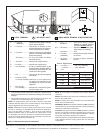
Note: Use SL-D Series
components only.
Note: There MUST be a 25%
reduction in total H when using
fl ex vent except when using the
simple up and out installation
(see Figure 5.3).
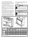
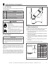
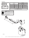
Fire Risk. Explosion Risk.
Do NOT pack insulation or other combustibles between ceiling fi restops.
• ALWAYS maintain specifi ed clearances around venting and fi restop systems.
• Install wall shield and ceiling fi restops as specifi ed.
Failure to keep insulation or other material away from vent pipe may cause fi re.
WARNING
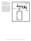
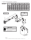
V
1
H
1
One Elbow
Fire Risk.
• When using SL-HRC-SS and SL-HRC-ZC-SS
termination caps on top vented fi replaces, a one
foot minimum vertical vent section is required
before installing fi rst elbow.
WARNING